DCMEASURING
DC MEASURING INSTRUMENTS
Understanding the functional design and operation of electrical measuring
instruments is very important, since they are used in repairing, maintaining,
and troubleshooting electrical circuits. While some meters can be used
for both dc and ac circuit measurement, only those used as dc instruments
are discussed in this section. The meters used for ac, or for both ac and
dc, are discussed in the study of ac theory and circuitry.
Effects of Current
The effect of current may be classified as follows: chemical, physiological,
photoelectric, piezoelectric, thermal, or electromagnetic.
Chemical
When an electric current is passed through certain solutions, a chemical
reaction takes place and a deposit forms on one electrode. The amount of
this deposit is proportional to the amount of current. Industrially, this
process is useful in electroplating and electrolysis. Although the chemical
effect is useful in defining the standard ampere (the amount of current
which causes 0.001118 grams of silver to be deposited in one second from
a 15 percent solution of silver nitrate), it is of no practical use in
meters.
Physiological
The physiological effect of current refers to the reaction of the human
body to an electric current.
An electric shock, although painful at times, is too difficult to evaluate
quantitatively and is, therefore, not practical for use in meters.
Photoelectric
When electrons strike certain materials, a glow appears at the point
of contact. The picture tube of a television set and the scope of a radar
set illustrate this effect. Using the intensity of the light produced as
a means of measuring the amount of current is neither accurate nor practical.
Piezoelectric
Certain crystals such as quartz and Rochelle salts become deformed when
a voltage is applied across two of the crystal faces. This effect is not
visible to the human eye and is, therefore, impractical for use in meters.
Thermal
When a current flows through a resistance, heat is produced. The amount
of heat produced is equal to I2R. This relationship establishes that heat
varies as the square of the current. Meters which employ the thermal effect
in their operation are common.
Electromagnetic
Whenever electrons flow through a conductor, a magnetic field proportional
to the current is created. This effect is useful for measuring current
and is employed in many practical meters.
The first four effects discussed are of no practical importance as electrical
measuring devices. The last two effects, thermal and magnetic, are of practical
use in meters. Since most of the meters in use have D'Arsonval movements,
which operate because of the magnetic effect, only this type will be discussed
in detail.
D'Arsonval Meter
The basic dc meter movement is known as the D'Arsonval meter movement
because it was first employed by the French scientist, D'Arsonval, in making
electrical measurement. This type of meter movement is a current measuring
device which is used in the ammeter, voltmeter, and ohmmeter. Basically,
both the ammeter and the voltmeter are current measuring instruments, the
principal difference being the method in which they are connected in a
circuit. While an ohmmeter is also basically a current measuring instrument,
it differs from the ammeter and voltmeter in that it provides its own source
of power and contains other auxiliary circuits.
Ammeter
The D'Arsonval ammeter is an instrument designed for measuring direct
current flowing in an electrical circuit and consists of the following
parts: a permanent magnet, a moving element mounting, bearings, and a case
which includes terminals, a dial, and screws. Each part and its function
are described in the discussion which follows.
The permanent magnet furnishes a magnetic field which will react with
the magnetic field set up by the moving element.
The moving element is mounted so that it is free to rotate when energized
by the current to be measured. A pointer which moves across a calibrated
scale is attached to this element. A moving coil mechanism is shown in
figure 8-121. The controlling element is a spring,
or springs, whose main function is to provide a counter or restoring force.
The strength of this force increases with the turning of the moving element
and brings the pointer to rest at some point on the scale. Two springs
are generally used; they are wound in opposite directions to compensate
for the expansion and contraction of the spring material due to temperature
variation. The springs are made of nonmagnetic material and conduct current
to and from the moving coil in some meters.
| The moving element consists of a shaft with very hard pivot
points to carry the moving coil or other movable element (figure
8-121). The pivot points are so fitted into highly polished jewels
or very hard glass bearings that the moving element can rotate with very
little friction.
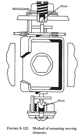
Another type of mounting has been designed in which the pivot points
are reversed and the bearings are inside the moving coil assembly. A method
of mounting moving elements is shown in figure 8-122.
The bearings are highly polished jewels such as sapphires, synthetic
jewels, or very hard glass. These are usually round and have a conical
depression in which the pivots rotate. They are set in threaded nuts which
allow adjustment. The radius of the depression in the jewel is greater
than the radius of the pivot point. This limits the area of contact surfaces
and provides a bearing which, when operated dry, probably has the lowest
constant friction value of any known type of bearing.
The case houses the instrument movement and protects it from mechanical
injury and exposure. It also has a window for viewing the movement of the
pointer across a calibrated scale. The dial has printed on it pertinent
information such as the scale, units of measurement, and meter uses. The
terminals are made of materials having very low electrical resistance.
Their function is to conduct the required current into and away from the
meter. |
|
Operation of the Meter Movement
The major units are mounted in their relationship to one another (figure
8-123). Note that the coil portion of the moving element is in the
magnetic field of the permanent magnet.
In order to understand how the meter works, assume that the coil of
the moving element is placed in a magnetic field as shown in figure
8-124.
The coil is pivoted so that it is able to rotate back and forth within
the magnetic field set up by the magnet. When the coil is connected in
a circuit, current flows through the coil in the direction indicated by
the arrows and sets up a magnetic field within the coil. This field has
the same polarity as the adjacent poles of the magnet. The interaction
of the two fields causes the coil to rotate to a position so that the two
magnetic fields are aligned.
This force of rotation (torque) is proportional to the interaction between
the like poles of the coil and the magnet and, therefore, to the amount
of current flow in the coil. As a result, a pointer attached to the coil
will indicate the amount of current flowing in the circuit as it moves
across a graduated scale.
In the arrangement just discussed, note that any torque sufficient to
overcome the inertia and friction of moving parts causes the coil to rotate
until the fields align. This uncontrolled movement would cause inaccurate
current readings. Therefore, the turning motion of the coil is opposed
by two springs. The value of the current flowing through the coil determines
the turning force of the coil. When the turning force is equal to the opposition
of the springs, the coil stops moving and the pointer indicates the current
reading on a calibrated scale. In some meters the springs are made of conducting
material and conduct current to and from the coil. The pole pieces of the
magnet form a circular air gap within which the coil is pivoted.
To obtain a clockwise rotation, the north pole of the permanent magnet
and that of the coil must be adjacent. The current flowing through the
coil must, therefore, always be in the same direction. The D'Arsonval movement
can be used only for dc measurements and the correct polarity must be observed.
If the current is allowed to flow in the wrong direction through the coil,
the coil will rotate counterclockwise and the pointer will be damaged.
Since the movement of the coil is directly proportional to the current
through the coil, the scale is normally a linear scale.
Damping
In order that meter readings can be made quickly and accurately, it
is desirable that the moving pointer overshoot its proper position only
a small amount and come to rest after not more than one or two small oscillations.
The term "damping" is applied to methods used to bring the pointer of an
electrical meter to rest after it has been set in motion. Damping may be
accomplished by electrical means, by mechanical means, or by a combination
of both.
|
Electrical Damping
A common method of damping by electrical means is to wind the moving
coil on an aluminum frame. As the coil moves in the field of the permanent
magnet, eddy currents are set up in the aluminum frame. The magnetic field
produced by the eddy currents opposes the motion of the coil. The pointer
will therefore swing more slowly to its proper position and come to rest
quickly with very little oscillation.
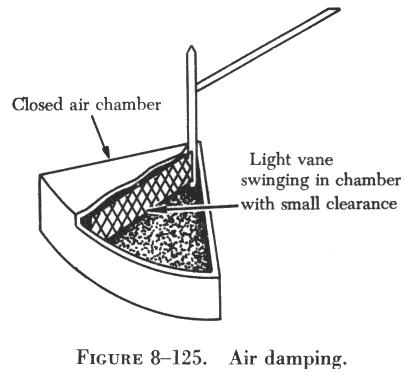
Mechanical Damping
Air damping is a common method of damping by mechanical means. As shown
in figure 8-125, a vane is attached to the shaft of the moving element
and enclosed in an air chamber. The movement of the shaft is retarded because
of the resistance which the air offers to the vane. Effective damping is
achieved if the vane nearly touches the walls of the chamber. |
|
Meter Sensitivity
The sensitivity of a meter movement is usually expressed as the amount
of current required to give full scale deflection. In addition, the sensitivity
may be expressed as the number of millivolts across the meter when full
scale current flows through it. This voltage drop is obtained by multiplying
the full scale current by the resistance of the meter movement. A meter
movement, whose resistance is 50 ohms and which requires 1 milliampere
(ma.) for full scale reading, may be described as a 50 millivolt 0 - 1
milliammeter.
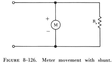
| Extending the Range of an Ammeter
A 0 - 1 milliammeter movement may be used to measure currents greater
than 1 ma. by connecting a resistor in parallel with the movement. The
parallel resistor is called a shunt because it bypasses a portion of the
current around the movement, extending the range of the ammeter.
A schematic drawing of a meter movement with a shunt connected across
it to extend its range is shown in figure 8-126. |
 |
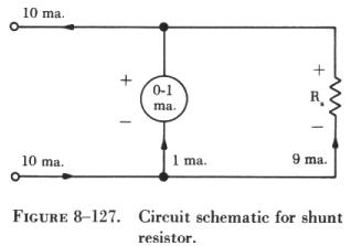 |
Determining the Value of a Shunt
The value of a shunt resistor can be computed by applying the basic
rules for parallel circuits. If a 50 millivolt 0 - 1 milliammeter is to
be used to measure values of current up to 10 ma., the following procedure
can be used: The first step involves drawing a schematic of the meter shunted
by a resistor labeled Rs (shunt resistor), as shown in figure 8-127. |
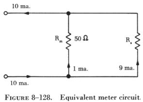
Since the sensitivity of the meter is known, the meter resistance can
be computed. The circuit is then redrawn as shown in figure 8-128, and
the branch currents can be computed, since a maximum of 1 ma. can flow
through the meter. The voltage drop across Rs is the same as that across
the meter, Rm:
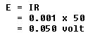
Rs can be found by applying Ohm's law: |
|
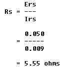
| The value of the shunt resistor (5.55 W) is very small, but this value
is critical. Resistors used as shunts must have close tolerances, usually
1 percent.
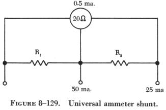
Universal Ammeter Shunt
The schematic drawing in figure 8-129, the universal shunt, shows an
arrangement whereby two or more ranges are provided by tapping the shunt
resistor at the proper points. In this arrangement, a 0 - 5 ma. movement
with a resistance of 20 ohms is shunted to provide a 0 - 25 ma. range and
a 0 - 50 ma. range. |
|
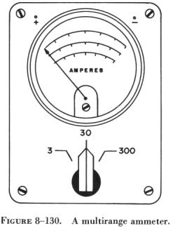 |
Ammeters having a number of internal shunts are called multirange ammeters.
A scale for each range is provided on the meter face (figure 8-130). Some
multimeters avoid internal switching through the use of external shunts.
Changing ammeter ranges involves the selection and installation on the
meter case of the proper size shunt.
|