DCMOTORS
DC MOTORS
Most devices in an airplane, from
the starter to the automatic pilot, depend upon mechanical energy furnished
by direct current motors. A direct current motor is a rotating machine
which transforms direct current energy into mechanical energy. It consists
of two principal parts - a field assembly and an armature assembly. The
armature is the rotating part in which current carrying wires are acted
upon by the magnetic field.
Whenever a current carrying wire
is placed in the field of a magnet, a force acts on the wire. The force
is not one of attraction or repulsion; however, it is at right angles to
the wire and also at right angles to the magnetic field set up by the magnet.
The action of the force upon a current carrying wire placed in a magnetic
field is shown in figure 9-67. A wire is located
between two permanent magnets. The lines of force in the magnetic field
are from the north pole to the south pole. When no current flows, as in
diagram A, no force is exerted on the wire, but when current flows through
the wire, a magnetic field is set up about it, as shown in diagram B. The
direction of the field depends on the direction of current flow. Current
in one direction creates a clockwise field about the wire, and current
in the other direction, a counterclockwise field.
Since the current carrying wire produces
a magnetic field, a reaction occurs between the field about the wire and
the magnetic field between the magnets. When the current flows in a direction
to create a counterclockwise magnetic field about the wire, this field
and the field between the magnets add or reinforce at the bottom of the
wire because the lines of force are in the same direction. At the top of
the wire, they subtract or neutralize, since the lines of force in the
two fields are opposite in direction. Thus, the resulting field at the
bottom is strong and the one at the top is weak. Consequently, the wire
is pushed upward as shown in diagram C of figure 9-67.
The wire is always pushed away from the side where the field is strongest.
If current flow through the wire
were reversed in direction, the two fields would add at the top and subtract
at the bottom. Since a wire is always pushed away from the strong field,
the wire would be pushed down.
Force Between Parallel Conductors
Two wires carrying current in the
vicinity of one another exert a force on each other because of their magnetic
fields. An end view of two conductors is shown in figure
9-68. In A, electron flow in both conductors is toward the reader,
and the magnetic fields are clockwise around the conductors. Between the
wires, the fields cancel because the directions of the two fields oppose
each other. The wires are forced in the direction of the weaker field,
toward each other. This force is one of attraction. In B, the electron
flow in the two wires is in opposite directions.
The magnetic fields are, therefore,
clockwise in one and counterclockwise in the other, as shown. The fields
reinforce each other between the wires, and the wires are forced in the
direction of the weaker field, away from each other. This force is one
of repulsion.
To summarize: Conductors carrying
current in the same direction tend to be drawn together; conductors carrying
current in opposite directions tend to be repelled form each other.
Developing Torque
If a coil in which current is flowing
is placed in a magnetic field, a force is produced which will cause the
coil to rotate. In the coil shown in figure 9-69,
current flows inward on side A and outward on side B. The magnetic field
about B is clockwise and that about A, counterclockwise. As previously
explained, a force will develop which pushes side B downward. At the same
time, the field of the magnets and the field about A, in which the current
is inward, will add at the bottom and subtract at the top. Therefore, A
will move upward. The coil will thus rotate until its plane is perpendicular
to the magnetic lines between the north and south poles of the magnet,
as indicated in figure 9-69 by the white coil at
right angles to the black coil.
| The tendency of a force
to produce rotation is called torque. When the steering wheel of a car
is turned, torque is applied. The engine of an airplane gives torque to
the propeller. Torque is developed also by the reacting magnetic fields
about the current carrying coil just described. This is the torque which
turns the coil.
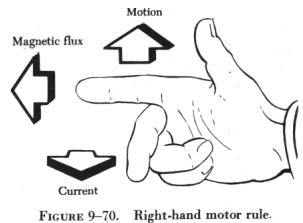
The right-hand motor rule can be
used to determine the direction a current carrying wire will move in a
magnetic field. As illustrated in figure 9-70, if the index finger of the
right hand is pointed in the direction of the magnetic field and the second
finger in the direction of current flow, the thumb will indicate the direction
the current carrying wire will move. |
|
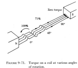 |
The amount of torque developed in
a coil depends upon several factors: the strength of the magnetic field,
the number of turns in the coil, and the position of the coil in the field.
Magnets are made of special steel which produces a strong field. Since
there is a torque acting on each turn, the greater the number of turns
on the coil, the greater the torque. In a coil carrying a steady current
located in a uniform magnetic field, the torque will vary at successive
positions of rotation, as shown in figure 9-71. When the plane of the coil
is parallel to the lines of force, the torque is zero. When its plane cuts
the lines of force at right angles, the torque is 100 percent. At intermediate
positions, the torque ranges between zero and 100 percent. |
Basic DC Motor
A coil of wire through which the
current flows will rotate when placed in a magnetic field. This is the
technical basis governing the construction of a dc motor.
Figure 9-72 shows
a coil mounted in a magnetic field in which it can rotate. However, if
the connecting wires from the battery were permanently fastened to the
terminals of the coil and there was a flow of current, the coil would rotate
only until it lined itself up with the magnetic field. Then, it would stop,
because the torque at that point would be zero.
A motor, of course, must continue
rotating. It is necessary, therefore, to design a device that will reverse
the current in the coil just at the time the coil becomes parallel to the
lines of force. This will create torque again and cause the coil to rotate.
If the current reversing device is set up to reverse the current each time
the coil is about to stop, the coil can be made to continue rotating as
long as desired.
One method of doing this is to connect
the circuit so that, as the coil rotates, each contact slides off the terminal
to which it connects and slides onto the terminal of opposite polarity.
In other words, the coil contacts switch terminals continuously as the
coil rotates, preserving the torque and keeping the coil rotating. In Figure
9-72, the coil terminal segments are labeled A and B. As the coil rotates,
the segments slide onto and past the fixed terminals or brushes. With this
arrangement, the direction of current in the side of the coil next to the
north seeking pole flows toward the reader, and the force acting on that
side of the coil turns it downward. The part of the motor which changes
the current from one wire to another is called the commutator.
When the coil is positioned as shown
in A of Figure 9-72, current will flow from the
negative terminal of the battery to the negative (-) brush, to segment
B of the commutator, through the loop to segment A of the commutator, to
the positive (+) brush, and then, back to the positive terminal of the
battery. By using the right-hand motor rule, it is seen that the coil will
rotate counterclockwise. The torque at this position of the coil is maximum,
since the greatest number of lines of force are being cut by the coil.
When the coil has rotated 90°
to the position shown in B of Figure 9-72, segments
A and B of the commutator no longer make contact with the battery circuit
and no current can flow through the coil. At this position, the torque
has reached a minimum value, since a minimum number of lines of force are
being cut. However, the momentum of the coil carries it beyond this position
until the segments again make contact with the brushes, and current again
enters the coil; this time, though, it enters through segment A and leaves
through segment B. However, since the positions of segments A and B have
also been reversed, the effect of the current is as before, the torque
acts in the same direction, and the coil continues its counterclockwise
rotation. On passing through the position shown in C of Figure
9-72, the torque again reaches maximum. Continued rotation carries
the coil again to a position of minimum torque, as in D of Figure
9-72. At this position, the brushes no longer carry current, but once
more the momentum rotates the coil to the point where current enters through
segment B and leaves through A. Further rotation brings the coil to the
starting point and, thus, one revolution is completed.
The switching of the coil terminals
from the positive to the negative brushes occurs twice per revolution of
the coil.
The torque in a motor containing
only a single coil is neither continuous nor very effective, for there
are two positions where there is actually no torque at all. To overcome
this, a practical dc motor contains a large number of coils wound on the
armature. These coils are so spaced that, for any position of the armature,
there will be coils near the poles of the magnet. This makes the torque
both continuous and strong. The commutator, likewise, contains a large
number of segments instead of only two.
The armature in a practical motor
is not placed between the poles of a permanent magnet but between those
of an electromagnet, since a much stronger magnetic field can be furnished.
The core is usually made of a mild or annealed steel, which can be magnetized
strongly by induction. The current magnetizing the electromagnet is from
the same source that supplies the current to the armature.
DC Motor Construction
The major parts in a practical motor
are the armature assembly, the field assembly, the brush assembly, and
the end frame. (See figure 9-73.)
Armature Assembly
The armature assembly contains a
laminated, soft iron core, coils, and a commutator, all mounted on a rotatable
steel shaft. Laminations made of stacks of soft iron, insulated from each
other, form the armature core. Solid iron is not used, since a solid iron
core revolving in the magnetic field would heat and use energy needlessly.
The armature windings are insulated copper wire, which are inserted in
slots insulated with fiber paper (fish paper) to protect the windings.
The ends of the windings are connected to the commutator segments. Wedges
or steel bands hold the windings in place to prevent them from flying out
of the slots when the armature is rotating at high speeds. The commutator
consists of a large number of copper segments insulated from each other
and the armature shaft by pieces of mica. Insulated wedge rings hold the
segments in place.
Field Assembly
The field assembly consists of the
field frame, the pole pieces, and the field coils. The field frame is located
along the inner wall of the motor housing. It contains laminated soft steel
pole pieces on which the field coils are wound. A coil, consisting of several
turns of insulated wire, fits over each pole piece and, together with the
pole, constitutes a field pole. Some motors have as few as two poles, others
as many as eight.
Brush Assembly
The brush assembly consists of the
brushes and their holders. The brushes are usually small blocks of graphitic
carbon, since this material has a long service life and also causes minimum
wear to the commutator. The holders permit some play in the brushes so
they can follow any irregularities in the surface of the commutator and
make good contact. Springs hold the brushes firmly against the commutator.
A commutator and two types of brushes are shown in figure
9-74.
End Frame
The end frame is the part of the
motor opposite the commutator. Usually, the end frame is designed so that
it can be connected to the unit to be driven. The bearing for the drive
end is also located in the end frame. Sometimes the end frame is made a
part of the unit driven by the motor. When this is done, the bearing on
the drive end may be located in any one of a number of places.