DRAWINGSYMBOLS DRAWING SYMBOLS
The drawings for a component are composed largely of symbols and conventions representing its shape and material. Symbols are the shorthand of drawing. They graphically portray the characteristics of a component, with a minimum amount of drawing.

Material Symbols

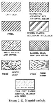
Section line symbols show the kind of material from which the part is to be constructed. The material may not be indicated symbolically when its exact specification must also be shown elsewhere on the drawing. In this case, the more easily drawn symbol for cast iron is used for the sectioning, and the material specification is listed in the bill of materials or indicated in a note. Figure 2-22 illustrates a few standard material symbols.

Shape Symbols

Symbols can be used to excellent advantage, when it is desired to show the shape of an object. Typical shape symbols used on aircraft drawings are shown in figure 2-23. Shape symbols are usually shown on a drawing as a revolved or removed section.

Electrical Symbols

Electrical symbols (figure 2-24) represent various electrical devices rather than an actual drawing of the units. Having learned what the various symbols indicate, it becomes relatively simple to look at an electrical diagram and determine what each unit is, what function it serves, and how it is connected in the system.