That part of the rectification process which involves the converting of an ac voltage into pulses of dc voltage has been treated in the discussion of vacuum tube, dry disk, and semiconductor diodes. To complete the rectification process so that the pulses of voltage are changed to an acceptable approximation of smooth dc involves a process called filtering.
Any reactance which opposes a change in voltage (or current) by storing energy and then releasing this energy back to the circuit may be used as a filter.
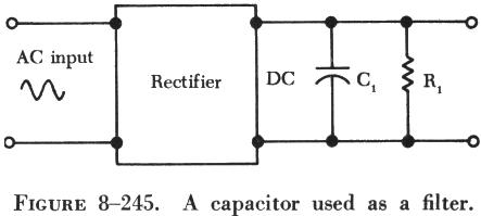
In the study of capacitors, it was demonstrated that a capacitance opposes a voltage change across its terminal by storing energy in its electrostatic field. Whenever the voltage tends to rise, the capacitor converts this voltage change to stored energy. When the voltage tends to fall, the capacitor converts this stored energy back to voltage. The use of a capacitor for filtering the output of a rectifier is illustrated in figure 8-245. The rectifier is shown as a block, and the capacitor C1 is connected in parallel with the load R1.
The capacitor C1 is chosen to offer very low impedance to the ac ripple frequency and very high impedance to the dc component. The ripple voltage is therefore bypassed to ground through the low impedance path, while the dc voltage is applied unchanged to the load. The effect of the capacitor on the output of the rectifier can be seen in the waveshapes shown in figure 8-246. Dotted lines show the rectifier output; solid lines show the effect of the capacitor. Fullwave rectifier outputs are shown. The capacitor C1 charges when the rectifier voltage output tends to increase and discharges when the voltage output tends to decrease. In this manner, the voltage across the load R1 is kept fairly constant.
An inductance may be used as a filter, because it opposes a change in
current through it by storing energy in its electromagnetic field whenever
current tends to increase. When the current through the inductor tends
to decrease, the inductor supplies the energy to maintain the flow of current.
The use of an inductor for filtering the output of a rectifier is shown
in figure 8-247. Note that the inductor L1 is in
series with the load R1.
| The inductance L1 is chosen to offer high impedance to the ac ripple voltage and low impedance to the dc component. Therefore, for the ac ripple, a very large voltage drop occurs across the inductor and a very small voltage drop across the load R1. For the dc component, however, a very small voltage drop occurs across the inductor and a very large voltage drop across the load. The effect of an inductor on the output of a fullwave rectifier in the output waveshape is shown in figure 8-248. Note that the ripple has been attenuated (reduced) in the output voltage. | 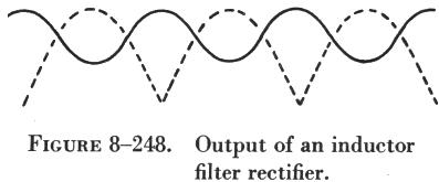 |
Capacitors and inductors are combined in various ways to provide more satisfactory filtering than can be obtained with a single capacitor or inductor. These are referred to collectively as "LC filters." Several combinations are shown schematically in figure 8-249. Note that the L, or inverted L-type, and the T-type filter sections resemble schematically the corresponding letters of the alphabet. The pi-type filter section resembles the Greek letter pi (p)schematically.
All the filter sections shown are similar in that the inductances are in series and the capacitances are in parallel with the load. The inductances must, therefore, offer a very high impedance and the capacitors a very low impedance to the ripple frequency. Since the ripple frequency is comparatively low, the inductances are iron core coils having large values of inductance (several henries). Because they offer such high impedance to the ripple frequency, these coils are called chokes. The capacitors must also be large (several microfarads) to offer very little opposition to the ripple frequency. Because the voltage across the capacitor is dc, electrolytic capacitors are frequently used as filter capacitors. The correct polarity in connecting electrolytic capacitors should always be observed.
Additional filter sections may be combined to improve the filtering
action.
| LC filters are also classified according to the position
of the capacitor and inductor. A capacitor input filter is one in which
the capacitor is connected directly across the output terminals of the
rectifier. A choke input filter is one in which a choke precedes the filter
capacitor.
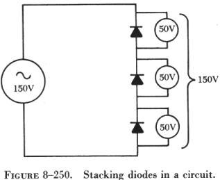
If it is necessary to increase the applied voltage to more than a single rectifier can tolerate, the usual solution is to stack them. These rectifiers are similar to resistors added in series. Each resistor will drop a portion of the applied voltage rather than the total voltage. The same theory applies to rectifiers added in series, or stacked. Series stacking increases the voltage rating. If, for example, a rectifier will be destroyed with an applied voltage exceeding 50 volts, and it is to be used in a circuit with an applied voltage of 150 volts, stacking of diodes can be employed. The result is shown in figure 8-250. |
 |
Identification of Semiconductor Diodes
There are many types of semiconductor diodes in existence today and several methods are used to identify the emitter and collector. The following are the three most common methods used to identify the emitter and collector.
One method places a small dot near the emitter lead (A of figure 8-251). A second method stamps the rectifier symbol on the diode case (B of figure 8-251). The third method used quite frequently is the color code method (C of figure 8-251). Frequently the color code used is the same as the color code used for resistors.
One very common diode is the 1N538. The "1N" indicates that there is
only one PN junction, or that the device is a diode; the numbers that follow
normally indicate manufacturing sequence; that is, a 1N537 was developed
before the 1N538, which may be an improved model of the 1N537 or may be
an entirely different diode altogether.