FUELSYSTEMCOMPONENTS
FUEL SYSTEM COMPONENTS
The basic components of a fuel system include tanks, lines, valves,
pumps, filtering units, gauges, warning signal, and primer. Some systems
will include central refueling provisions, fuel dump valves, and a means
for transferring fuel. In order to clarify the operating principles of
complex aircraft fuel systems, the various units are discussed in the following
paragraphs.
| Fuel Tanks
The location, size, shape, and construction of fuel tanks vary with
the type and intended use of the aircraft. In some aircraft, the fuel tanks
are integral with the wing or other structural portions of the aircraft.
Fuel tanks are made of materials that will not react chemically with
any aviation fuel. Aluminum alloy is widely used, and synthetic rubber
bladder-type fuel cells are used in some installations.
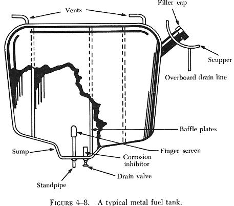
Usually a sump and a drain are provided at the lowest point in the tank
as shown in figure 4-8. When a sump or low point is provided in the tank,
the main fuel supply is not drawn from the bottom of the sump, but from
a higher point in the tank.
The top of each tank is vented to the outside air in order to maintain
atmospheric pressure within the tank. Air vents are designed to minimize
the possibility of their stoppage by |
|
dirt and ice formation. In order to permit rapid changes in internal air
pressure, the size of the vent is proportional to the size of the tank,
thus preventing the collapse of the tank in a steep dive or glide. All
except the very smallest of tanks are fitted with internal baffles to resist
fuel surging caused by changes in the attitude of the aircraft. Usually
an expansion space is provided in fuel tanks to allow for an increase in
fuel volume due to expansion.
The filler neck and cap are usually located in a recessed well, equipped
with a scupper and drain. The scupper is designed to prevent overflowing
fuel from entering the wing or fuselage structure. Fuel caps have provisions
for locking devices to prevent accidental loss during flight. Filler openings
are clearly marked with the word "FUEL", the tank capacity, and the type
of fuel to be used. Information concerning the capacity of each tank is
usually posted near the fuel selector valves, as well as on the tank filler
caps.
Some fuel tanks are equipped with dump valves that make it possible
to jettison fuel during flight in order to reduce the weight of the aircraft
to its specified maximum landing weight. In aircraft equipped with dump
valves, the operating control is located within reach of the pilot, copilot,
or flight engineer. Dump valves are designed and installed to afford safe,
rapid discharge of fuel.
Fuel Cells
Present day aircraft may be equipped with one or more of the following
types of fuel cells: the bladder-type fuel cell and the integral fuel cell.
Bladder-Type Fuel Cells
The bladder-type fuel cell is a nonselfsealing cell that is used to
reduce weight. It depends entirely upon the structure of the cavity in
which it sits to support the weight of the fuel within it. For this reason,
the cell is made slightly larger than the cavity. The bladder cells in
use are made either of rubber or of nylon.
Integral Fuel Cells
Since integral fuel cells are usually built into the wings of the aircraft
structure, they are not removable. An integral cell is a part of the aircraft
structure, which has been so built that after the seams, structural fasteners,
and access doors have been properly sealed, the cell will hold fuel without
leaking. This type of construction is usually referred to as a "wet wing."
Fuel Lines and Fittings
In an aircraft fuel system, the various tanks and other components are
usually joined together by fuel lines made of metal tubing connected, where
flexibility is necessary, by lengths of flexible hose. The metal tubing
usually is made of aluminum alloy, and the flexible hose is made of synthetic
rubber or Teflon. The diameter of the tubing is governed by the fuel flow
requirements of the engine.
Each fuel line is identified by a color coded band near each end. Except
for short lines between flexible connections, tubing should be properly
supported by clamping to structural members of the aircraft.
A special heat resistant hose is used where the flexible lines will
be subjected to intense heat. For all flexible fuel lines located forward
of the firewall, fire resistant hose is used.
In many installations, the fuel lines are designed to be located within
the tanks. Therefore, minor leaks occurring within the tank are classified
as internal leaks and will not cause fire hazards.
| Fuel Strainers
Strainers are installed in the tank outlets and frequently in the tank
filler necks. These are of fairly coarse mesh and prevent only the larger
particles from entering the fuel system. Other, fine mesh, strainers are
provided in the carburetor fuel inlets and in the fuel lines.
The function of the main strainer is important: it not only prevents
foreign matter from entering the carburetor, but also, because of its location
at the low point of the fuel system, traps any small amount of water that
may be present in the system. In multiengine aircraft, one main strainer
is usually installed in each engine nacelle.
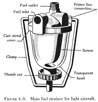
A main fuel strainer for a light airplane is shown in figure 4-9. It
consists of a cast metal top, a screen, and a glass bowl. The bowl is attached
to the cover by a clamp and thumb nut. Fuel enters the unit through the
inlet port, filters through the screen, and exits through the outlet port.
At regular intervals the glass bowl is drained, and the screen is removed
for inspection and cleaning. |
|
The main fuel strainer shown in figure 4-10 is
so installed that the fuel flows through it before reaching the engine
driven pump. It is located at the lowest point in the fuel system.
The shape and construction of the fine mesh screen provides a large
screening surface encased in a compact housing. Reinforcing the screen
is a coarse, heavy wire mesh.
 |
Auxiliary Fuel Pumps
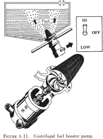
The electrically driven centrifugal booster pump, shown in figure 4-11,
supplies fuel under pressure to the inlet of the engine driven fuel pump.
This type of pump is an essential part of the fuel system, particularly
at high altitudes, to keep the pressure on the suction side of the engine
driven pump from becoming low enough to permit the fuel to boil. This booster
pump is also used to transfer fuel from one tank to another, to supply
fuel under pressure for priming when starting the engine, and, as an emergency
unit, to supply fuel to the carburetor in case the engine driven pump fails.
To increase the capacity of the pump under emergency conditions, many pumps
are equipped with a two speed or variable speed control so that the recommended
fuel inlet pressure to the carburetor can be maintained. As a precautionary
measure, the booster pump is always turned on during takeoffs and landings
to ensure a positive supply of fuel.
The booster pump is mounted at the tank outlet within a detachable sump
or is submerged in fuel at the bottom of the fuel tank. The seals between
the impeller and the power section of the pump prevent leakage of fuel
or fumes into the motor. If any liquid or vapor should leak past the seal,
it is vented overboard through a drain. As an added precaution in nonsubmerged-type
pumps, air is allowed to circulate around the motor to remove dangerous
fuel vapor. |
As fuel enters the pump from the tank, a high speed impeller throws
the fuel outward in all directions at high velocity. The high rotational
speed swirls the fuel and produces a centrifuge action that separates air
and
vapor from the fuel before it enters the fuel line to the carburetor. This
results in practically vapor free fuel delivery to the carburetor and permits
the separated vapors to rise through the fuel tank and escape through the
tank vents. Since a centrifugal-type pump is not a positive displacement
pump, no relief valve is necessary.
Although the centrifugal type is the most common type of booster pump,
there are still a few sliding vane-type booster pumps in service. This
type, too, is driven by an electric motor. Unlike the centrifugal type,
it does not have the advantage of the centrifuge action to separate the
vapor from the fuel. Since it is a positive displacement type pump, it
must have a relief valve to prevent excessive pressure. Its construction
and operation are identical to the engine driven pump.
Hand Pump
The hand, or wobble, pump is frequently used on light aircraft. It is
generally located near other fuel system components and operated from the
cockpit by suitable controls. A diagram of a wobble pump is shown in figure
4-12. When the handle attached to the central blade is operated, the
low pressure created on the chamber below the upward moving blade, permits
the incoming fuel pressure to lift the lower flapper and allows fuel to
flow into this chamber. At the same time fuel flows through a drilled passageway
to fill the chamber above the downward moving blade. As the blade moves
downward, the lower flapper closes, preventing fuel from escaping back
into the inlet line. The fuel below the downward moving blade flows through
a passageway into another chamber and is discharged through an outlet flapper
valve to the carburetor. The cycle is repeated each time the handle is
moved in either direction.
Engine Driven Fuel Pump
The purpose of the engine driven fuel pump is to deliver a continuous
supply of fuel at the proper pressure at all times during engine operation.
The pump widely used at the present time is the positive displacement,
rotary vane-type pump.
A schematic diagram of a typical engine driven pump (vane-type) is shown
in figure 4-13. Regardless of variations in design,
the operating principle of all vane-type fuel pumps is the same.
The engine driven pump is usually mounted on the accessory section of
the engine. The rotor, with its sliding vanes, is driven by the crankshaft
through the accessory gearing. Note how the vanes carry fuel from the inlet
to the outlet as the rotor turns in the direction indicated. A seal prevents
leakage at the point where the drive shaft enters the pump body, and a
drain carries away any fuel that leaks past the seal. Since the fuel provides
enough lubrication for the pump, no special lubrication is necessary.
Since the engine driven fuel pump normally discharges more fuel than
the engine requires, there must be some way of relieving excess fuel to
prevent excessive fuel pressures at the fuel inlet of the carburetor. This
is accomplished through the use of a spring loaded relief valve that can
be adjusted to deliver fuel at the recommended pressure for a particular
carburetor. Figure 4-13, shows the pressure relief
valve in operation, bypassing excess fuel back to the inlet side of the
pump. Adjustment is made by increasing or decreasing the tension of the
spring.
The relief valve of the engine driven pump is designed to open at the
set pressure regardless of the pressure of the fuel entering the pump.
To maintain the proper relation between fuel pressure and carburetor inlet
air pressure, the chamber above the fuel pump relief valve is vented either
to the atmosphere or through a balance line to carburetor air inlet pressure.
The combined pressures of spring tension and either atmospheric or carburetor
inlet air pressure determine the absolute pressure at which the relief
valve opens. This balanced-type relief valve has certain objectionable
features that must be investigated when encountering fuel system troubles.
A syphon or diaphragm failure will allow air to enter the fuel on the inlet
side of the pump if the pump inlet pressure is less than atmospheric. Conversely,
if the pump inlet pressure is above atmospheric pressure, fuel will be
discharged from the vent. For proper altitude compensation the vent must
be open. If it should become clogged by ice or foreign matter while at
altitude, the fuel pressure will decrease during descent. If the vent becomes
clogged during ascent, the fuel pressure will increase as the altitude
is increased.
In addition to the relief valve, the fuel pump has a bypass valve that
permits fuel to flow around the pump rotor whenever the pump is inoperative.
This valve, shown in figure 4-14, consists of a
disk that is lightly spring loaded against a series of ports in the relief
valve head. When fuel is needed for starting the engine, or in the event
of engine driven pump failure, fuel at booster pump pressure is delivered
to the fuel pump inlet. When the pressure is great enough to move the bypass
disk from its seat, fuel is allowed to enter the carburetor for priming
or metering. When the engine driven pump is in operation, the pressure
built up on the outlet side of the pump, together with the pressure of
the bypass spring, holds the disk on its seat and prevents fuel flow through
the ports.
Valves
Selector valves are installed in the fuel system to provide a means
for shutting off the fuel flow, for tank and engine selection, for crossfeed,
and for fuel transfer. The size and number of ports (openings) vary with
the type of installation. For example, a single engine aircraft with two
fuel tanks and a reserve fuel supply requires a valve with four ports -
three inlets from the tanks and a common outlet. The valve must accommodate
the full flow capacity of the fuel line, must not leak, and must operate
freely with a definite "feel" or "click" when it is in the correct position.
Selector valves may be operated either manually or electrically. A tube,
rod, or cable is attached to a manually operated valve so that it can be
operated from the cockpit. Electrically operated valves have an actuator,
or motor. The three main types of selector valves are the poppet, cone,
and disk.
The poppet-type selector valve has an individual poppet valve at each
inlet port. A cam and yoke on the same shaft act to open the selected poppet
valve as the yoke is turned. Figure 4-15 shows how
the cam lifts the upper poppet valve from its seat when the control handle
is set to the "number 2" tank. This opens the passage from the "number
2" tank to the engine. At the same time, a raised portion of the index
plate drops into a notch in the side of the cam. (See the detail of the
index mechanism.) This produces the "feel" that indicates the valve is
in the wide open position. The control handle should always be set by "feel"
rather than by the marking on the indicator dial. The index mechanism also
keeps the valve in the desired position and prevents creeping caused by
vibration. Some valves have more than one raised portion on the cam to
allow two or more ports to be opened at the same time.
The cone-type selector valve has either an all metal or a cork faced
aluminum housing. The cone, which fits into the housing, is rotated by
means of a cockpit control. To supply fuel from the desired tank, the cockpit
control is turned until the passages in the cone align with the correct
ports in the housing. An indexing mechanism aids in obtaining the desired
setting and also holds the cone in the selected position. Some cone-type
valves have a friction release mechanism that reduces the amount of turning
torque required to make a tank selection and that can be adjusted to prevent
leakage.
The rotor of the disk-type selector valve fits into a cylindrical hole
in the valve body. A disk-type valve is shown in figure
4-16. Note that the rotor has one open port and several sealing disks
- one for each port in the housing. To select a tank, the rotor is turned
until the open port aligns with the port from which fuel flow is desired.
At this time, all other ports are closed by the sealing disks. In this
position, fuel will flow from the desired tank to the selector valve and
out through the engine feed port at the bottom of the valve. To ensure
positive port alignment for full fuel flow, the indexing mechanism (shown
in the center of figure 4-16 forces a spring loaded
ball into a ratchet ring. When the selector valve is placed in the closed
position, the open port in the rotor is opposite a blank in the valve body,
while each scaling disk covers a tank port.
Fuel tank shutoff valves have two positions, open and closed. They are
installed in the system to prevent fuel loss when a fuel system component
is being removed or when a part of the system is damaged. In some installations
they are used to control the fuel flow during fuel transfer. They are operated
either manually or electrically. An electrically operated fuel shutoff
valve includes a reversible electric motor linked to a sliding valve assembly.
The motor moves the valve gate in and out of the passage through which
the fuel flows, thus, shutting off or turning on the fuel flow.