FUELSYSTEMINDICATORS
FUEL SYSTEM INDICATORS
Fuel Quantity Gauges
Fuel quantity gauges are necessary so that the operator may know the
quantity of fuel remaining in the tanks during operation of the aircraft.
The four general types of fuel gauges are: (1) Sight glass, (2) mechanical,
(3) electrical, and (4) electronic. The type of fuel gauge installation
depends on the size of the aircraft and the number and location of the
fuel tanks. Since the sight glass and mechanical fuel gauges are not suitable
for aircraft where tanks are located an appreciable distance from the cockpit,
larger aircraft use either electrical or electronic fuel quantity gauges.
On some aircraft, one fuel gauge, called a totalizer, indicates the total
amount of fuel remaining in all the fuel tanks. The sight glass is the
simplest form of fuel quantity gauge. The indicator is a glass or plastic
tube placed on the same level as the tank. It operates on the principle
that a liquid seeks its own level.
The tube is calibrated in gallons or has a metal scale near it. The
sight glass may have a shutoff valve so that the fuel can be shut off for
cleaning and for preventing loss of fuel if the tube is broken.
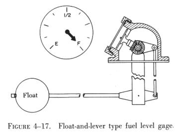
| The mechanical-type fuel quantity gauge is usually located
in the tank and is known as a direct reading gauge. It has an indicator
connected to a float resting on the surface of the fuel. As the fuel level
changes, the float mechanically operates the indicator, thus showing the
level of fuel in the tank. One type of mechanical fuel gauge is illustrated
in figure 4-17.
The electrical-type quantity gauge consists of an indicator in the cockpit
and a float operated transmitter installed in the tank. As the fuel level
changes, the transmitter sends an electric signal to the indicator, which
shows the changing fuel level. Two important advantages of this fuel quantity
gauge (and the electronic type discussed in the next paragraph) are that
the indicator can be located any distance from the tank and the fuel levels
of several tanks can be read on one indicator. |
|
The electronic-type (capacitance) fuel quantity gauge differs from the
other types in that it has no movable devices in the fuel tank. Instead
of floats and their attendant mechanical units, the dielectric qualities
of fuel and air furnish a measurement of fuel quantity. Essentially, the
tank transmitter is a simple electric condenser. The dielectric (or nonconducting
material) of the condenser is fuel and air (vapor) above the fuel. The
capacitance of the tank unit at any one time will depend on the existing
proportion of fuel and vapors in the tank. The capacitance of the transmitter
is compared to a reference capacitor in a rebalance-type bridge circuit.
The unbalanced signal is amplified by the voltage amplifiers that drive
a phase discriminating power stage. The output stage supplies power to
one phase of a two phase ac motor that mechanically drives a rebalancing
potentiometer and indicator pointer. The electronic type system of measuring
fuel quantity is more accurate in measuring fuel level, as it measures
the fuel by weight instead of in gallons. Fuel volume will vary with temperature
(a gallon of gasoline weighs more when it is cold than when it is hot);
thus, if it is measured in pounds instead of gallons, the measurement will
be more accurate.
In addition to the cockpit fuel quantity indicating system, some aircraft
are provided with a means to determine the fuel quantity in each tank when
the aircraft is on the ground. This is accomplished in several different
ways. Some manufacturers use float operated, direct reading fuel gauges
mounted in the lower surface of the wing. Another means is to use under
wing bayonet gauges. There are two types in use, the drip gauge and the
sight gauge.
When using the drip gauge it is necessary to proceed slowly, using the
trial and error method to find the exact fuel level. In large area tanks
a proportionately large amount of fuel is represented by a fraction of
an inch variation in fuel level. The long, hollow drip tubes require some
time to drain once they are filled with fuel, and a substantial error in
reading will be made if the diminishing drainage drip is mistaken for the
steady drip that signifies that the tube is properly positioned.
When the cap and hollow drip tube are drawn out from the lower wing
surface, the fuel enters the open top of the tube when it reaches the level
of the fuel. As stated previously steady drip from a drip hole signifies
that the tube is properly positioned with a tiny head of fuel above the
opening. The drip gauge tube may be calibrated in pounds or inches. When
calibrated in inches, the reading is compared with a special chart to give
a reading of fuel quantity in gallons.
The sight gauge is somewhat simpler in construction than the drip gauge,
and offers unmistakable visual evidence when it is properly positioned
for reading. As shown in figure 4-18, the sight
gauge is basically a long lucite rod, protected by a calibrated tube, which
terminates at the top in an exposed quartz tip. When the tip is above the
fuel it acts as a reflector.
Light rays traveling up the lucite rod are deflected at right angles
by the 45° surface at one side of the tip and deflected 90° again
by the 45° surface at the opposite side and returned down the lucite
rod.
Any portion of the tip submerged in fuel will not act as a reflector.
Consequently, when the fuel level is part way up the taper, a light pattern
is created that is visible at the lower end of the lucite rod and that
has the dimension and shape described by the intersection of the tip and
the fuel. When the reflected light is reduced to the smallest perceptible
point in the case of cone tipped gauges, or hairline in the case of chisel
tipped gauges, the rod is properly positioned. The fuel tank quantity can
be read on the tube where it emerges from the recessed guide housing. Drip
gauge readings are taken at this location also.
Fuel Flowmeter
The fuel flowmeter is normally used only in multiengine aircraft. The
system consists of a transmitter and an indicator. The transmitter is installed
in the fuel inlet line to the engine, where it measures the rate of fuel
flow. The transmitter is electrically connected to the indicator located
in the cockpit. This gauge shows the rate of fuel consumption in pounds
per hour.
The transmitter signal may be developed by a movable vane mounted in
the fuel flow path. The impact of fuel causes the vane to swing and move
against the restraining force of a calibrated spring. The final position
assumed by the vane represents a measure of the rate at which fuel is passing
through the flowmeter and the corresponding signal to be sent to the indicator.
A vane-type fuel flowmeter system is illustrated in figure
4-19.
The transmitter used with turbine engines is the mass flow type having
a range of 500 to 2,500 pounds per hour. It consists of two cylinders placed
in the fuel stream so that the direction of fuel flow is parallel to the
axes of the cylinders. (See figure 4-20.) The cylinders
have small vanes in the outer periphery. The upstream cylinder, called
the impeller, is driven at a constant angular velocity by the power supply.
This velocity imparts an angular momentum to the fuel. The fuel then transmits
this angular velocity to the turbine (the downstream cylinder), causing
the turbine to rotate until a restraining spring force balances the force
due to the angular momentum of the fuel. The deflection of the turbine
positions a magnet in the second harmonic transmitter to a position corresponding
to the fuel flow. The turbine position is transmitted to the flight station
indicator by means of a selsyn system.
 |
Fuel Pressure Gauge
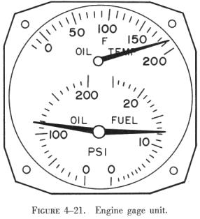
The fuel pressure gauge indicates the pressure of the fuel entering
the carburetor. This gauge may be included with the oil pressure gauge
and the oil temperature gauge in one casing, called the engine gauge unit.
Most aircraft today have separate gauges for these functions. An engine
gauge unit is shown in figure 4-21.
The fuel pressure gauge is a differential pressure indicator with two
connections on the back of the indicator housing. The air connection (see
figure 4-22) is vented to the carburetor air inlet,
and the fuel connection is attached to the fuel inlet chamber of the carburetor.
In this way the gauge indicates the difference between the fuel pressure
entering the carburetor and the air pressure at the carburetor air inlet.
In some installations, the air fitting on the gauge is left open to the
air pressure of the cockpit, which is |
generally the same as the pressure of the atmosphere. When this venting
arrangement is used, the relief valve of the engine driven
fuel pump is also vented to the atmosphere, and the gauge indicates
the fuel pressure resulting from the adjusted spring pressure only. In
order to dampen pressure pulsations that cause pointer fluctuation, a restrictor
fitting (A) is installed at the carburetor end of the fuel gauge line.
(See the Y connection shown in figure 4-22.) The
second restrictor (B) meters fuel to the oil system during oil dilution.
The arrangement of these restrictors provides an indicated drop in fuel
pressure when the oil dilution system is used.
The oil dilution system will be discussed thoroughly in the Powerplant
Handbook, and is mentioned at this time only because the fuel pressure
indicator provides a means for a check on the operation of other fuel system
units.
In small aircraft the fuel pressure gauge may be actuated by a Bourdon
tube (an instrument that converts changes in pressure to mechanical motion),
or an aneroid and bellows type, installed with a pressure line leading
directly from the carburetor to the indicator. On larger aircraft, where
the fuel pressure gauge is located some distance from the carburetor, a
transmitter is usually installed. The pressure transmitter may be a simple
cast metal cell that is divided into two chambers by a flexible diaphragm.
Pressure applied by the fuel source to the transmitter inlet pushes against
the diaphragm and builds up an equal pressure to a thin fluid (highly refined
kerosene), which transfers the pressure to the indicator mechanism. Some
installations, however, use electrical transmitters to register fuel pressure
on the gauge. In this electrical arrangement, the pressure indicating unit
is contained in the transmitter. Fuel pressure, acting upon the aneroid
and bellows portion of the unit, causes motion of one part of an electrical
unit
 |
(the synchro transmitter). As the unit turns, it causes a similar movement
of a corresponding unit (the synchro motor). This receiving unit actuates
the indicator on the instrument panel. These pressure and electrical arrangements
make it unnecessary for combustible fuel to enter the cockpit or flight
deck, thereby reducing fire risk.
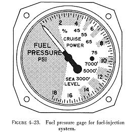
A fuel pressure gauge often used with fuel injection systems on light
aircraft engines is illustrated in figure 4-23. A gauge of this type registers
metered fuel pressure at the fuel injection unit distributor valve and
is a direct indication of engine power output when installed in a fuel
injection system for light aircraft engines. The dial of the gauge is marked
to indicate percent of power. The gauge does not indicate either the engine
driven pump or the boost pump pressure. |
Pressure Warning Signal
In an aircraft with several tanks, there is always the possible danger
of allowing the fuel supply in one tank to become exhausted before the
selector valve is switched to another. To prevent this, pressure warning
signals are installed in some aircraft. The complete installation, shown
in figure 4-22, consists of a pressure sensitive
mechanism and a warning light. The warning mechanism has both a fuel and
an air connection.
The connection marked "fuel" is connected to the fuel pressure line
of the carburetor. The air connection is vented to either atmospheric or
carburetor air inlet pressure. This arrangement prevents the warning mechanism
from acting in response to changes in the absolute pressure of the fuel.
If, for example, the absolute pressure of the fuel decreases because of
a change in atmospheric or carburetor air inlet pressure, the change is
also reflected at the warning mechanism, which then cancels the effects
of the change. Normal fuel pressure against the power surface of the diaphragm
holds the electrical contacts apart. When the fuel pressure drops below
specified limits, the contacts close and the warning light is turned on.
This alerts the operator to take whatever action is necessary to boost
the fuel pressure.
Valve In Transit Indicator Lights
On large multiengine aircraft, each of the fuel crossfeed and line valves
may be provided with a valve in transit indicator light. This light is
on only during the time the valve is in motion and is off when movement
is complete.
Fuel Temperature Indicator
A means for checking the temperature of the fuel in the tanks and at
the engine is provided on some turbine powered aircraft. During extreme
cold, especially at altitude, the gauge can be checked to determine when
fuel temperatures are approaching those at which there may be danger of
ice crystals forming in the fuel.