 |
|
|
|
||
|
INVERTERS An inverter is used in some aircraft systems to convert a portion of the aircraft's dc power to ac. This ac is used mainly for instruments, radio, radar, lighting, and other accessories. These inverters are usually built to supply current at a frequency of 400 cps, but some are designed to provide more than one voltage; for example, 26 volt ac in one winding and 115 volts in another. There are two basic types of inverters: the rotary and the static. Either type can be single phase or multiphase. The multiphase inverter is lighter for the same power rating than the single phase, but there are complications in distributing multiphase power and in keeping the loads balanced. Rotary Inverters There are many sizes, types, and configurations of rotary inverters. Such inverters are essentially ac generators and dc motors in one housing. The generator field, or armature, and the motor field, or armature, are mounted on a common shaft which will rotate within the housing. One common type of rotary inverter is the permanent magnet inverter. Permanent Magnet Rotary Inverter A permanent magnet inverter is composed of a dc motor and a permanent magnet ac generator assembly. Each has a separate stator mounted within a common housing. The motor armature is mounted on a rotor and connected to the dc supply through a commutator and brush assembly. The motor field windings are mounted on the housing and connected directly to the dc supply. A permanent magnet rotor is mounted at the opposite end of the same shaft as the motor armature, and the stator windings are mounted on the housing, allowing ac to be taken from the inverter without the use of brushes. Figure 9-60 shows an internal wiring diagram for this type of rotary inverter. The generator rotor has six poles, magnetized to provide alternate north and south poles about its circumference. When the motor field and armature are excited, the rotor will begin to turn. As the rotor turns, the permanent magnet will rotate within the ac stator coils, and the magnetic flux developed by the permanent magnets will be cut by the conductors in the ac stator coils. An ac voltage will be produced in the windings whose polarity will change as each pole passes the windings. This type inverter may be made multiphase by placing more ac stator coils in the housing in order to shift the phase the proper amount in each coil. As the name of the rotary inverter indicates, it has a revolving armature in the ac generator section. The illustration in figure 9-61 shows the diagram of a revolving armature, three phase inverter. The dc motor in this inverter is a four pole, compound wound motor. The four field coils consist of many turns of fine wire, with a few turns of heavy wire placed on top. The fine wire is the shunt field, connected to the dc source through a filter and to ground through a centrifugal governor. The heavy wire is the series field, which is connected in series with the motor armature. The centrifugal governor controls the speed by shunting a resistor which is in series with the shunt field when the motor reaches a certain speed. |
|
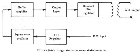
The alternator is a three phase, four pole, star connected ac generator. The dc input is supplied to the generator field coils and connected to ground through a carbon pile voltage regulator. The output is taken off the armature through three slip rings to provide three phase power. The inverter would be a single phase inverter if it had a single armature winding and one slip ring. The frequency of this type unit is determined by the speed of the motor and the number of generator poles. Inductor-Type Rotary Inverter Inductor-type inverters use a rotor made of soft iron laminations with grooves cut laterally across the surface to provide poles that correspond to the number of stator poles, as illustrated in figure 9-62. The field coils are wound on one set of stationary poles and the ac armature coils on the other set of stationary poles. When dc is applied to the field coils, a magnetic field is produced. The rotor turns within the field coils and, as the poles on the rotor align with the stationary poles, a low reluctance path for flux is established from the field pole through the rotor poles to the ac armature pole and through the housing back to the field pole. In this circumstance, there will be a large amount of magnetic flux linking the ac coils. When the rotor poles are between the stationary poles, there is a high reluctance path for flux, consisting mainly of air; then, there will be a small amount of magnetic flux linking the ac coils. This increase and decrease in flux density in the stator induces an alternating current in the ac coils. The frequency of this type of inverter is determined by the number of poles and the speed of the motor. The voltage is controlled by the dc stator field current. A cutaway view of an inductor-type rotary inverter is shown in figure 9-63. Figure 9-64 is a simplified diagram of a typical aircraft ac power distribution system, utilizing a main and a standby rotary inverter system. Static Inverters In many applications where continuous dc voltage must be converted to alternating voltage, static inverters are used in place of rotary inverters or motor generator sets. The rapid progress being made by the semiconductor industry is extending the range of applications of such equipment into voltage and power ranges which would have been impractical a few years ago. Some such applications are power supplies for frequency sensitive military and commercial ac equipment, aircraft emergency ac systems, and conversion of wide frequency range power to precise frequency power. The use of static inverters in small aircraft also has increased rapidly in the last few years, and the technology has advanced to the point that static inverters are available for any requirement filled by rotary inverters. For example, 250 VA emergency ac supplies operated from aircraft batteries are in production, as are 2,500 VA main ac supplies operated from a varying frequency generator supply. This type of equipment has certain advantages for aircraft applications, particularly the absence of moving parts and the adaptability to conduction cooling. Static inverters, referred to as solid state inverters, are manufactured in a wide range of types and models, which can be classified by the shape of the ac output waveform and the power output capabilities. One of the most commonly used static inverters produces a regulated sine wave output. A block diagram of a typical regulated sine wave static inverter is shown in figure 9-65. This inverter converts a low dc voltage into higher ac voltage. The ac output voltage is held to a very small voltage tolerance, a typical variation of less than 1 percent with a full input load change. Output taps are normally provided to permit selection of various voltages; for example, taps may be provided for a 105, 115, and 125 volt ac outputs. Frequency regulation is typically within a range of one cycle for a 0 - 100 percent load change.
Variations of this type of static inverter are available, many of which provide a square wave output. Since static inverters use solid state components, they are considerably smaller, more compact, and much lighter in weight than rotary inverters. Depending on the output power rating required, static inverters that are no larger than a typical airspeed indicator can be used in aircraft systems. Some of the features of static inverters are: 1. High efficiency.
Static inverters are commonly used to provide power for such frequency sensitive instruments as the attitude gyro and directional gyro. They also provide power for autosyn and magnesyn indicators and transmitters, rate gyros, radar, and other airborne applications. Figure 9-66 is a schematic of a typical small jet aircraft auxiliary battery system. It shows the battery as input to the inverter, and the output inverter circuits to various subsystems. |
| ©AvStop Online Magazine Contact Us Return to Airframe & Powerplant General Handbook |