 |
|
|
|
||
|
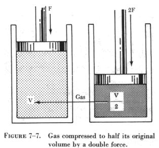
KINETIC THEORY OF GASES The simple structure of gases makes them readily adaptable to mathematical analysis from which has evolved a detailed theory of the behavior of gases. This is called the kinetic theory of gases. The theory assumes that a body of gas is composed of identical molecules which behave like minute elastic spheres, spaced relatively far apart and continuously in motion. The degree of molecular motion is dependent upon the temperature of the gas. Since the molecules are continuously striking against each other and against the walls of the container, an increase in temperature with the resulting increase in molecular motion causes a corresponding increase in the number of collisions between the molecules. The increased number of collisions results in an increase in pressure because a greater number of molecules strike against the walls of the container in a given unit of time. If the container were an open vessel, the gas would expand and overflow from the container. However, if the container is sealed and possesses elasticity (such as a rubber balloon), the increased pressure causes the container to expand. For instance, when making a long drive on a hot day, the pressure in the tires of an automobile increases, and a tire which appeared to be somewhat "soft" in cool morning temperature may appear normal at a higher midday temperature. Such phenomena as these have been explained and set forth in the form of laws pertaining to gases and tend to support the kinetic theory. At any given instant, some molecules of a gas are moving in one direction, some in another direction; some are traveling fast while some are traveling slowly; some may even be in a state of rest. The combined effect of these varying velocities corresponds to the temperature of the gas. In any considerable amount of gas, there are so many molecules present that in accordance with the "laws of probability" some average velocity can be found. If this average velocity were possessed by every molecule in the gas, it would produce the same effect at a given temperature as the total of the many varying velocities. Boyle's Law As previously stated, compressibility is an outstanding characteristic of gases. The English scientist Robert Boyle was among the first to study this characteristic which he called the "springiness of air." By direct measurement he discovered that when the temperature of a combined sample of gas was kept constant and the pressure doubled, the volume was reduced to half the former value; as the applied pressure was decreased, the resulting volume increased. From these observations, he concluded that for a constant temperature the product of the volume and pressure of an enclosed gas remains constant. Boyle's law is normally stated: "The volume of an enclosed dry gas varies inversely with its pressure, provided the temperature remains constant." |
|
Substituting:
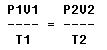
A gas which conforms to Boyle's law is termed an ideal gas. When pressure is increased upon such a gas, its volume decreases proportionally and its density is increased. Thus, the density of a gas varies directly with the pressure, if the temperature remains constant as in the case of an ideal gas. Density also varies with temperature, since gases expand when heated and contract when cooled. The useful applications of Boyle's law are many and varied. Some applications more common to aviation are: (1) The carbon dioxide (CO2) bottle used to inflate life rafts and life vests; (2) the compressed oxygen and the acetylene tanks used in welding; (3) the compressed air brakes and shock absorbers; and (4) the use of oxygen tanks for high altitude flying and emergency use. Charles' Law The French scientist Jacques Charles provided much of the foundation for the modern kinetic theory of gases. He found that all gases expand and contract in direct proportion to the change in the absolute temperature, provided the pressure is held constant. In equation form, this part of the law may be expressed.
This equation means that with a constant volume, the absolute pressure of a gas varies directly with the absolute temperature. Examples of Charles' law: A cylinder of gas under a pressure of 1,800 psig at 70° F is left out in the sun in the tropics and heats up to a temperature of 130° F. What is the new pressure within the cylinder? The pressure and temperature must be converted to absolute pressure and temperature. Formula or equation:
Using the Rankine system: 70° F = 530° absolute
Substituting:
Then:
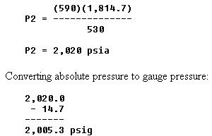
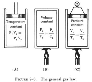
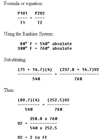
An examination of figure 7-8 reveals that the three equations are special cases of the general equation. Thus, if the temperature remains constant, T1 equals T2, and both can be eliminated from the general formula, which then reduces to the form shown in (A). When the volume remains constant, V1 equals V2, reducing the general equation to the form given in (B). Similarly P1 is equated to P2 for constant pressure, and the equation then takes the form given in (C). The general gas law applies with exactness only to "ideal" gases in which the molecules are assumed to be perfectly elastic. However, it describes the behavior of actual gases with sufficient accuracy for most practical purposes. Two examples of the general equation follow: 1. Two cu ft of a gas at 75 psig and 80° F are compressed to a volume of 1 cu ft and then heated to a temperature of 300° F. What is the new gauge pressure? Formula or equation:
Using the Rankine system:
Substituting:
Then:
Converting absolute pressure to gauge pressure:
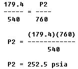
2. Four cubic feet of a gas at 75 psig and 80° F are compressed to 237.8 psig and heated to a temperature of 300° F. What is the volume of the gas resulting from these changes?
Avogadro's Law An Italian physicist, Avogadro, conceived the theory that "at the same temperature and pressure, equal volumes of different gases contain equal numbers of molecules." This theory was proven by experiment and found to agree with the kinetic theory, so it has come to be known as Avogadro's law.
Pascal's Law
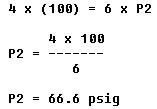
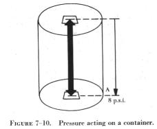
Therefore, the liquid remains at rest; it does not leak out and the tank does not collapse. One of the consequences of Pascal's law is that the shape of the container in no way alters pressure relations. Thus, in figure 7-11, if the pressure due to the weight of the liquid at one point on the horizontal line (H) is 8 psi, the pressure is 8 psi everywhere at level (H) in the system. Pressure due to the weight of a fluid depends, at any level, on the height of the fluid from the level to the surface of the fluid. The vertical distance between two horizontal levels in a fluid is known as the head of the fluid. In figure 7-11, the liquid head of all points on level (H) with respect to the surface is indicated. Pressure due to fluid head also depends on the density of the fluid. Water, for example, weighs 62.4 lbs/cu ft or 0.036 lb/cu in, but a certain oil might weigh 55 lbs/cu ft, or 0.032 lb/cu in. To produce a pressure of 8 psi, it would take 222 inches of head using water, and 252 inches of head using the oil (see figure 7-12). Force and Pressure In order to understand how Pascal's law is applied to fluid power, a distinction must be made between the terms "force" and "pressure." Force may be defined as a push or pull. It is the push or pull exerted against the total area of a particular surface and is expressed in pounds. As previously stated, pressure is the amount of force on a unit area of the surface acted upon. In hydraulics and pneumatics, pressure is expressed in pounds per square inch. Thus, pressure is the amount of force acting upon 1 square inch of area. Computing Force, Pressure, and Area A formula, similar to those used with the gas laws, is used in computing force, pressure, and area in fluid power systems. Although there appears to be three formulas, it is only one formula written in three variations, where P refers to pressure, F indicates force, and A represents area. Force equals pressure times area. Thus, the formula is written: F = P x A Pressure equals force divided by the area. By rearranging the formula, this statement is condensed into:
Since area equals force divided by pressure, the formula is written:
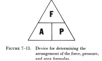
Figure 7-13 illustrates a device for recalling these formulas. Any letter in the triangle may be expressed as the product or quotient of the other two, depending upon its position within the triangle.
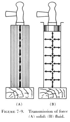
For example, to find area, consider the letter "A" as being set off by itself, followed by an equal sign. Now look at the other two letters. The letter "F" is above the letter "P"; therefore, A = F / P In order to find pressure, consider the letter "P" as being set off by itself, and look at the other two letters. The letter "F" is above the letter "A"; therefore, P = F / A In a similar manner, to find force, consider the letter "F" as being set off by itself. The letters "P" and "A" are side by side; therefore, F = P x A. Sometimes the area may not be expressed in square inches. If it is a rectangular surface, the area may be found by multiplying the length (in inches) by the width (in inches). The majority of areas to be considered in these calculations are circular. Either the diameter or the radius (one half the diameter) may be given. The radius in inches must be known to find the area. Then, the formula for finding the area of a circle is used. This is written A = p x r2, where A is the area, pi is 3.1416 (3.14 or 3 1/7 for most calculations), and r2 indicates radius squared. Pressure and Force in Fluid Power Systems In accordance with Pascal's law, any force applied to a confined fluid is transmitted equally in all directions throughout the fluid regardless of the shape of the container. Consider the effect of this in the system shown in figure 7-14, which is a modification of B in figure 7-9. The column of fluid is curved upward to its original level, with a second piston at this point. It is clear that when the input piston (1) is pushed downward, a pressure is created through the fluid, which acts equally at right angles to surfaces in all parts of the container. Referring to figure 7-14, if the force (1) is 100 lbs and the area of the piston is 10 sq in, then the pressure in the fluid is 10 psi (100/10). This pressure acts on piston (2), so that for each square inch of its area it is pushed upward with a force of 10 pounds. In this case, a fluid column of uniform cross section is considered so that the area of the output piston (2) is the same as the input piston (1), or 10 square inches. Therefore, the upward force on the output piston (2) is 100 pounds, the same as applied to the input piston (1). All that has been accomplished in this system was to transmit the 100 pound force around a bend. However, this principle underlies practically all mechanical applications of fluid power. At this point it should be noted that since Pascal's law is independent of the shape of the container, it is not necessary that the tube connecting the two pistons be the full area of the pistons. A connection of any size, shape, or length will do if an unobstructed passage is provided. Therefore, the system shown in figure 7-15, in which a relatively small, bent tube connects two cylinders, will act exactly the same as that shown in figure 7-14. Multiplication of Forces In figure 7-14 and figure 7-15 the systems contain pistons of equal area in which the output force is equal to the input force. Consider the situation in figure 7-16, where the input piston is much smaller than the output piston. Assume that the area of the input piston (1) is 2 sq in. Pushing down on the input piston (1) with a force of 20 pounds creates 10 psi (20/2) in the fluid. Although this force is much smaller than the applied force in figure 7-14 and figure 7-15, the pressure is the same. This is because the force is concentrated on a relatively small area. This pressure of 10 psi acts on all parts of the fluid container, including the bottom of the output piston (2). The upward force on the output piston (2) is therefore 10 pounds for each of its 20 square inches of area, or 200 pounds (10 x 20). In this case, the original force has been multiplied tenfold while using the same pressure in the fluid as before. Obviously, the system would work just the same for any other forces and pressures, so that the ratio of output force to input force is always the same. The system works the same in reverse. Consider piston (2) in figure 7-16 as the input and piston (1) as the output. Then the output force will always be one-tenth the input force. Sometimes such results are desired. Therefore, if two pistons are used in a fluid power system, the force acting on each is directly proportional to its area, and the magnitude of each force is the product of the pressure and its area. Differential Areas Consider the special situation shown in figure 7-17. Here, a single piston in a cylinder has a piston rod attached to one side of the piston which extends out of the cylinder at one end. Fluid under pressure is admitted to both ends of the cylinder equally through tubes. The opposed faces of the piston behave like two pistons acting against each other. The area of one face is the full area of the cylinder, for example, 6 sq in. The area of the other face is the area of the cylinder minus the area of the piston rod, which is 2 sq in, leaving an effective area of 4 sq in on the right face of the piston. The pressure on both faces is the same, in this case, 20 psi. Applying the rule just stated, the force pushing the piston to the right is its area times the pressure, or 120 pounds (20 x 6). Similarly, the force pushing it to the left is its area times the pressure, or 80 pounds. Therefore, there is a net unbalanced force of 40 pounds acting to the right, and the piston will move in that direction. The net effect is the same as if the piston and cylinder were just the size of the piston rod, since all other forces are in balance. Volume and Distance Factors In the systems illustrated in figure 7-14 and figure 7-15, the pistons have areas of 10 sq in each. Therefore, if one of these pistons is pushed down 1 inch, 10 cu in of fluid is displaced. Since liquid is practically incompressible, this volume must go somewhere. In the case of a gas, it will compress momentarily, but will eventually expand to its original volume. Thus, this volume moves the other piston. Since the area of this piston is also 10 sq in, it will move 1 inch in order to accommodate the 10 cu in of fluid. The pistons are of equal areas, and will therefore move equal distances, though in opposite directions. Applying this reasoning to the system in figure 7-16, it is obvious that if the input piston (1) is pushed down 1 inch, only 2 cu in of fluid is displaced. In order to accommodate these 2 cu in of fluid, the output piston (2) will have to move only one-tenth of an inch, because its area is 10 times that of the input piston (1). This leads to the second basic rule for two pistons in the same fluid power system, which is, that the distances moved are inversely proportional to their areas. Effects of Atmospheric Pressure Atmospheric pressure, described previously, obeys Pascal's law the same as pressure set up in fluids. As illustrated in figure 7-14, pressures due to a liquid head are distributed equally in all directions. This is also true of atmospheric pressures. The situation is the same if these pressures act on opposite sides of any surface, or through fluids. In A of figure 7-18 the suspended sheet of paper is not torn by atmospheric pressure, as it would be by an unbalanced force, because atmospheric pressure acts equally on both sides of the paper. In B of figure 7-18, atmospheric pressure acting on the surface of the liquid is transmitted equally throughout the liquid to the walls of the container, but is balanced by the same pressure acting directly on the outer walls of the container. In C of figure 7-18, atmospheric pressure acting on the surface of one piston is balanced by the same pressure acting on the surface of the other. The different areas of the two surfaces make no difference, since for a unit of area, the pressures are in balance. Bernoulli's Principle Bernoulli's principle was originally stated to explain the action of a liquid flowing through the varying cross-sectional areas of tubes. In figure 7-19 a tube is shown in which the cross-sectional area gradually decreases to a minimum diameter in its center section. A tube constructed in this manner is called a "venturi," or "venturi tube." As a liquid (fluid) flows through the venturi tube, the three vertical tubes act as pressure gauges, filling with liquid until the pressure of the liquid in each tube equals the pressure of the moving liquid in the venturi. The venturi in figure 7-19 can be used to illustrate Bernoulli's principle, which states that: The pressure of a fluid (liquid or gas) decreases at points where the velocity of the fluid increases. In the wide section of the venturi (points A and C of figure 7-19), the liquid moves at low velocity, producing a high pressure, as indicated by the height of the liquid in the vertical tubes at these two points. As the tube narrows in the center, it must contain the same volume of fluid as the two end areas. In this narrow section, the liquid moves at a higher velocity, producing a lower pressure than that at points A and C, as indicated by the height of the column of liquid in the vertical tube above point B of figure 7-19. The venturi principle, in any of a number of shapes and sizes, is used in aircraft systems. They may be referred to as restrictions or orifices. For example, an orifice is generally installed in a hydraulic line to limit the rate of fluid flow. A hydraulically operated aircraft landing gear, when being extended, will tend to drop with great speed because of the weight of the mechanism. If a restrictor is installed in the hydraulic return line the extension of the gear will be slowed, thus preventing possible structural damage. |
||||||||||
| ©AvStop Online Magazine Contact Us Return to Airframe & Powerplant General Handbook |