 |
|
|
|
||
|
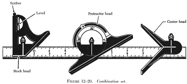
LAYOUT AND MEASURING TOOLS Layout and measuring devices are precision tools. They are carefully machined, accurately marked and, in many cases, are made up of very delicate parts. When using these tools, be careful not to drop, bend, or scratch them. The finished product will be no more accurate than the measurements or the layout; therefore, it is very important to understand how to read, use, and care for these tools. Rules Rules are made of steel and are either rigid or flexible. The flexible steel rule will bend, but it should not be bent intentionally as it may be broken rather easily. In aircraft work the unit of measure most commonly used is the inch. The inch may be divided into smaller parts by means of either common or decimal fraction divisions. The fractional divisions for an inch are found by dividing the inch into equal parts - halves (1/2), quarters (1/4), eighths (1/8), sixteenths (1/16), thirty-seconds (1/32), and sixty-fourths (1/64) - as shown in figure 12-17. The fractions of an inch may be expressed in decimals, called decimal equivalents of an inch; for example, 1/8 inch is expressed as 0.0125 (one hundred twenty-five ten-thousandths of an inch). Rules are manufactured in two basic styles, those divided or marked in common fractions (figure 12-19) and those divided or marked in decimals or divisions of one one-hundredth of an inch. A rule may be used either as a measuring tool or as a straightedge. Combination Sets The combination set (figure 12-20), as its name implies, is a tool that has several uses. It can be used for the same purposes as an ordinary tri-square, but it differs from the tri-square in that the head slides along the blade and can be clamped at any desired place. Combined with the square or stock head are a level and scriber. The head slides in a central groove on the blade or scale, which can be used separately as a rule.
|
|
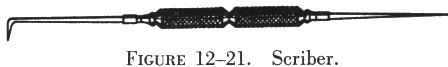
The spirit level in the stock head makes it convenient to square a piece of material with a surface and at the same time tell whether one or the other is plumb or level. The head can be used alone as a simple level. The combination of square head and blade can also be used as a marking gauge to scribe lines at a 45° angle, as a depth gauge, or as a height gauge. A convenient scriber is held frictionally in the head by a small brass bushing. The center head is used to find the center of shafts or other cylindrical work. The protractor head can be used to check angles and also may be set at any desired angle to draw lines. Scriber The scriber is designed to serve the aviation mechanic in the same way a pencil or pen serves a writer. In general, it is used to scribe or mark lines on metal surfaces. The scriber (figure 12-21) is made of tool steel, 4 to 12 inches long, and has two needle pointed ends. One end is bent at a 90° angle for reaching and marking through holes.
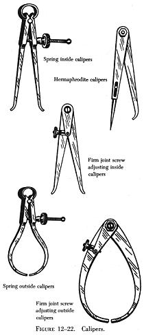
Before using a scriber always inspect the points for sharpness. Be sure the straightedge is flat on the metal and in position for scribing. Tilt the scriber slightly in the direction toward which it will be moved, holding it like a pencil. Keep the scriber's point close to the guiding edge of the straightedge. The scribed line should be heavy enough to be visible, but no deeper than necessary to serve its purpose. Dividers and Pencil Compasses Dividers and pencil compasses have two legs joined at the top by a pivot. They are used to scribe circles and arcs and for transferring measurements from the rule to the work. Pencil compasses have one leg tapered to a needle point; the other leg has a pencil or pencil lead inserted. Dividers have both legs tapered to needle points. When using pencil compasses or dividers, the following procedures are suggested: 1. Inspect the points to make sure they are sharp. 2. To set the dividers or compasses, hold them with the point of one leg in the graduations on the rule. Turn the adjustment nut with the thumb and forefinger; adjust the dividers or compasses until the point of the other leg rests on the graduation of the rule which gives the required measurement. 3. To draw an arc or circle with either the pencil compasses or dividers, hold the thumb attachment on the top with the thumb and forefinger. With pressure exerted on both legs, swing the compass in a clockwise direction and draw the desired arc or circle. 4. The tendency for the legs to slip is avoided by inclining the compasses
or dividers in the direction in which they are being rotated. In working
on metals, the dividers are used only to scribe arcs or circles that will
later be removed by cutting. All other arcs or circles are drawn with pencil
compasses to avoid scratching the material.
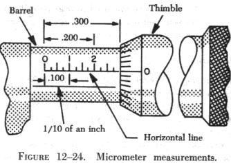
All four types of micrometers are read in the same way. The method of reading an outside micrometer is discussed later in this chapter. Micrometer Parts The fixed parts of a micrometer (figure 12-23) are the frame, barrel, and anvil. The movable parts of a micrometer are the thimble and spindle. The thimble rotates the spindle which moves in the threaded portion inside the barrel. Turning the thimble provides an opening between the anvil and the end of the spindle where the work is measured. The size of the work is indicated by the graduations on the barrel and thimble. Reading a Micrometer
These divisions are marked for convenience at every five spaces by 0, 5, 10, 15, and 20. When 25 of these graduations have passed the horizontal line on the barrel, the spindle (having made one revolution) has moved 0.025 inch. The micrometer is read by first noting the last visible figure on the horizontal line of the barrel representing tenths of an inch. Add to this the length of barrel between the thimble and the previously noted number. (This is found by multiplying the number of graduations by 0.025 inch.) Add to this the number of divisions on the bevel edge of the thimble that coincides with the line of the graduation. The total of the three figures equals the measurement. (Figure 12-25 shows several sample readings.) Vernier Scale Some micrometers are equipped with a vernier scale which makes it possible to read directly the fraction of a division that may be indicated on the thimble scale. Typical examples of the vernier scale as it applies to the micrometer are shown in figure 12-26. All three scales on a micrometer are not fully visible without turning the micrometer; but the examples shown in figure 12-26 are drawn as though the barrel and thimble of the micrometer were laid out flat so that all three scales can be seen at the same time. The barrel scale is the lower horizontal scale; the thimble scale is vertical on the right; and the long horizontal lines (0 through 9 and 0) make up the vernier scale. In reading a micrometer, an excellent way to remember the relative scale values is to remember that the 0.025 inch barrel scale graduations are established by the lead screw (40 threads per inch). Next, the thimble graduations divide the 0.025 inch into 25 parts, each equal to 0.001 inch; then the vernier graduations divide the 0.001 inch into 10 equal parts, each equal to 0.0001 inch. Remembering the values of the various scale graduations, the barrel scale reading is noted. The thimble scale reading is added to it; then the vernier scale reading is added to get the final reading. The vernier scale line to be read is always the one aligned exactly with any thimble graduation. In the first example in figure 12-26, the barrel reads 0.275 inch and the thimble reads more than 0.019 inch. The number 1 graduation on the thimble is aligned exactly with the number 4 graduation on the vernier scale. Thus, the final reading is 0.2944 inch. In the second example in figure 12-26, the barrel reads 0.275 inch, and the thimble reads more than 0.019 inch and less than 0.020 inch. On the vernier scale, the number 7 graduation coincides with a line on the thimble. This means that the thimble reading would be 0.0197 inch. Adding this to the barrel reading of 0.275 inch gives a total measurement of 0.2947 inch. The third and fourth examples in figure 12-26 are additional readings that would require use of the vernier scale for accurate readings to ten-thousandths of an inch. Using a Micrometer The micrometer must be handled carefully. If it is dropped, its accuracy may be permanently affected. Continually sliding work between the anvil and spindle may wear the surfaces. If the spindle is tightened too much, the frame may be sprung permanently and inaccurate readings will result. To measure a piece of work with the micrometer, hold the frame of the micrometer in the palm of the hand with the little finger or third finger, whichever is more convenient. This allows the thumb and forefinger to be free to revolve the thimble for adjustment. |
||||
| ©AvStop Online Magazine Contact Us Return to Airframe & Powerplant General Handbook |