 |
Airframe & Powerplant
|
|
|
|
|||
|
LEAD-ACID BATTERIES
|
|||
|
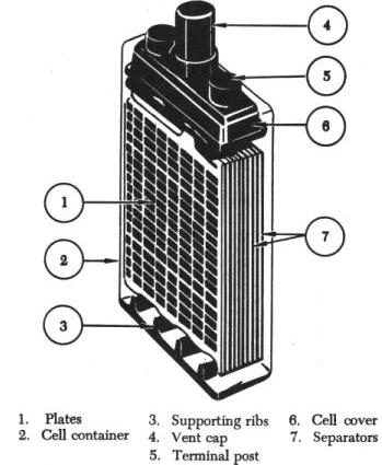
Each cell is seated in a hard rubber casing through the top of which are terminal posts and a hole into which is screwed a nonspill vent cap (4). The hole provides access for testing the strength of the electrolyte and adding water. |
The other is the exhaust vent tube and is attached to the battery drain sump, which is a glass jar containing a felt pad moistened with a concentrated solution of sodium bicarbonate (baking soda). With this arrangement, the airstream is directed through the battery case where battery gases are picked up, neutralized in the sump, and then expelled overboard without damage to the airplane.
Additionally, a cell approaching a state of total discharge is of little use because the high internal resistance (IR) caused by the sulfate coatings on its plates reduces the current to a value too low for practical use. When a cell is being charged, lead sulfate is removed from both the positive and negative plates, and sulfuric acid is again formed. In the process, the water content of the electrolyte is decreased and the density of the electrolyte is increased. The open circuit voltage of a lead-acid cell, that is, its voltage when there is no load drawing current, is approximately 2.2 volts. This voltage is the same for every lead-acid cell regardless of its plate size and remains at this value until the cell is practically dead, regardless of its state of discharge. When the cell approaches total discharge, its voltage begins to drop rapidly. The closed circuit voltage of a cell, that is, its voltage under load, decreases gradually as the cell is discharged. This gradual decrease in terminal voltage is due to a gradual increase in the internal resistance of the cell caused by sulphation of the plates. At the end of normal discharge, the internal resistance of a lead-acid cell is more than twice as high as it is when fully charged. The difference between the open circuit and closed circuit terminal voltages is due to the voltage drop inside the cell. This is equal to the current the load draws multiplied by the internal resistance in the cell. Therefore, the discharging voltage that a lead-acid cell can supply under closed circuit conditions is equal to the open circuit voltage of the cell minus the IR drop in the cell. To give a high discharge current and a high terminal voltage under load, a battery must have low internal resistance. This characteristic can be achieved through extensive plate area. Therefore, each cell contains several sets of plates. All the positive plates of a cell are connected by one connecting bar, and all the negative plates by another. Thus, the plates are connected in parallel, further decreasing the internal resistance of the cell. The open circuit cell voltage is not affected; it remains the same as that of a single pair of plates. Lead-Acid Battery Ratings The voltage of a battery is determined by the number of cells connected in series to form the battery. Although the voltage of one lead-acid cell just removed from a charger is approximately 2.2 volts, a lead-acid cell is normally rated at only 2 volts, because it soon drops to that value. A battery rated at 12 volts consists of 6 lead-acid cells connected in series, and a battery rated at 24 volts is composed of 12 cells. The capacity of a storage battery is rated in ampere-hours (amperes furnished by the battery times the amount of time current can be drawn). This rating indicates how long the battery may be used at a given rate before it becomes completely discharged. Theoretically, a 100 ampere-hour battery will furnish 100 amperes for 1 hour, 50 amperes for 2 hours, or 20 amperes for 5 hours. Actually, the ampere-hour output of a particular battery depends on the rate at which it is discharged. Heavy discharge current heats the battery and decreases its efficiency and total ampere-hour output. For airplane batteries, a period of 5 hours has been established as the discharge time in rating battery capacity. However, this time of 5 hours is only a basis for rating and does not necessarily mean the length of time during which the battery is expected to furnish current. Under actual service conditions, the battery can be completely discharged within a few minutes, or it may never be discharged if the generator provides sufficient charge. The ampere-hour capacity of a battery depends upon its total effective plate area. Connecting batteries in parallel increases ampere-hour capacity. Connecting batteries in series increases the total voltage but not the ampere-hour capacity. In multiengine airplanes, where more than one battery is used, the batteries are usually connected in parallel. The voltage is equal to that of one battery, but the ampere-hour capacity is increased. The total capacity is the sum of the ampere-hour ratings for the individual batteries. Factors Affecting Lead-Acid Battery Life Various factors cause deterioration of a battery and shorten its service life. These include over discharging, which causes excess sulphation and too rapid charging or discharging, resulting in overheating of the plates and shedding of active material. The accumulation of shedded material, in turn, causes shorting of the plates and results in internal discharge. A battery that remains in a low or discharged condition for a long period of time may be permanently damaged. In addition to causing deterioration of the battery, these factors also decrease battery capacity. Lead-Acid Battery Testing Methods The state of charge of a storage battery depends upon the condition of its active materials, primarily the plates. However, the state of charge of a battery is indicated by the density of the electrolyte and is checked by a hydrometer, an instrument which measures the specific gravity (weight as compared with water) of liquids. The hydrometer commonly used consists of a small sealed glass tube weighted at its lower end so it will float upright, as shown in figure 8-109. Within the narrow stem of the tube is a paper scale with a range of 1.100 to 1.300. When a hydrometer is used, a quantity of electrolyte sufficient to float the hydrometer is drawn up into the syringe. The depth to which the hydrometer sinks into the electrolyte is determined by the density of the electrolyte, and the scale value indicated at the level of the electrolyte is its specific gravity. The more dense the electrolyte, the higher the hydrometer will float; therefore, the highest number on the scale (1.300) is at the lower end of the hydrometer scale. In a new, fully charged aircraft storage battery, the electrolyte is approximately 30 percent acid and 70 percent water (by volume) and is 1.300 times as heavy as pure water. During discharge, the solution (electrolyte) become less dense and its specific gravity drops below 1.300. A specific gravity reading between 1.300 and 1.275 indicates a high state of charge; between 1.275 and 1.240, a medium state of charge; and between 1.240 and 1.200, a low state of charge. Aircraft batteries are generally of small capacity but are subject to heavy loads. The values specified for state of charge are therefore rather high. Hydrometer tests are made periodically on all storage batteries installed in aircraft. An aircraft battery in a low state of charge may have perhaps 50 percent charge remaining, but is nevertheless considered low in the face of heavy demands which would soon exhaust it. A battery in such a state of charge is considered in need of immediate recharging. When a battery is tested using a hydrometer, the temperature of the electrolyte must be taken into consideration. The specific gravity readings on the hydrometer will vary from the actual specific gravity as the temperature changes. No correction is necessary when the temperature is between 70° F and 90° F, since the variation is not great enough to be considered. When temperatures are greater than 90° F or less than 70° F, it is necessary to apply a correction factor. Some hydrometers are equipped with a correction scale inside the tube. With other hydrometers it is necessary to refer to a chart provided by the manufacturer. In both cases, the corrections should be added to, or subtracted from, the reading shown on the hydrometer. The specific gravity of a cell is reliable only if nothing has been added to the electrolyte except occasional small amounts of distilled water to replace that lost as a result of normal evaporation. Hydrometer readings should always be taken before adding distilled water, never after. This is necessary to allow time for the water to mix thoroughly with the electrolyte and to avoid drawing up into the hydrometer syringe a sample which does not represent the true strength of the solution. Extreme care should be exercised when making the hydrometer test of a lead-acid cell. The electrolyte should be handled carefully, for sulfuric acid will burn clothing and skin. If the acid does contact the skin the area should be washed thoroughly with water and then bicarbonate of soda applied. Lead-Acid Battery Charging Methods A storage battery may be charged by passing direct current through the battery in a direction opposite to that of the discharge current. Because of the internal resistance (IR) in the battery, the voltage of the external charging source must be greater than the open circuit voltage. For example, the open circuit voltage of a fully charged 12 cell, lead-acid battery is approximately 26.4 volts (12 x 2.2 volts), but approximately 28 volts are required to charge it. This larger voltage is needed for charging because of the voltage drop in the battery caused by the internal resistance. Hence, the charging voltage of a lead-acid battery must equal the open circuit voltage plus the IR drop within the battery (product of the charging current and the internal resistance). Batteries are charged by either the constant voltage or constant current method. In the constant voltage method (A of figure 8-110), a motor generator set with a constant, regulated voltage forces the current through the battery. In this method, the current at the start of the process is high but automatically tapers off, reaching a value of approximately 1 ampere when the battery is fully charged. The constant voltage method requires less time and supervision than does the constant current method. In the constant current method (B of figure 8-110), the current remains almost constant during the entire charging process. This method requires a longer time to charge a battery fully and, toward the end of the process, presents the danger of overcharging, if care is not exercised. In the aircraft, the storage battery is charged by direct current from the aircraft generator system. This method of charging is the constant voltage method, since the generator voltage is held constant by use of a voltage regulator. When a storage battery is being charged, it generates a certain amount of hydrogen and oxygen. Since this is an explosive mixture, it is important that steps be taken to prevent ignition of the gas mixture. The vent caps should be loosened and left in place. No open flames, sparks, or other source of ignition should be permitted in the vicinity. Before disconnecting or connecting a battery to the charge, always turn off the power by means of a remote switch. |
||||||||
| ©AvStop Online Magazine Contact Us Return to Airframe & Powerplant General Handbook |