Magnetic particle inspection is a method of detecting invisible cracks and other defects in ferromagnetic materials, such as iron and steel. This method of inspection is a nondestructive test, which means it is performed on the actual part without damage to the part. It is not applicable to nonmagnetic materials.
In rapidly rotating, reciprocating, vibrating, and other highly stressed aircraft parts, small defects often develop to the point that they cause complete failure of the part. Magnetic particle inspection has proved extremely reliable for the rapid detection of such defects located on or near the surface. In using this method of inspection, the location of the defect is indicated and the approximate size and shape are outlined.
The inspection process consists of magnetizing the part and then applying ferromagnetic particles to the surface area to be inspected. The ferromagnetic particles (indicating medium) may be held in suspension in a liquid that is flushed over the part; the part may be immersed in the suspension liquid; or the particles, in dry powder form, may be dusted over the surface of the part. The wet process is more commonly used in the inspection of aircraft parts.
If a discontinuity is present, the magnetic lines of force will be disturbed and opposite poles will exist on either side of the discontinuity. The magnetized particles thus form a pattern in the magnetic field between the opposite poles. This pattern, known as an "indication," assumes the approximate shape of the surface projection of the discontinuity. A discontinuity may be defined as an interruption in the normal physical structure or configuration of a part such as a crack, forging lap, seam, inclusion, porosity, and the like. A discontinuity may or may not affect the usefulness of a part.
Development of Indications
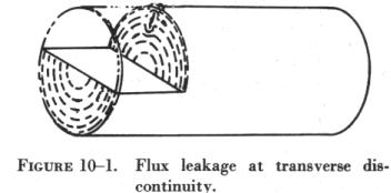
When a discontinuity in a magnetized material is open to the surface and a magnetic substance in the form of an indicating medium is available on the surface, the flux leakage at the discontinuity tends to form the indicating medium into a path of higher permeability. (Permeability is a term used to refer to the ease with which a magnetic flux can be established in a given magnetic circuit.) Because of the magnetism in the part and the adherence of the magnetic particles to each other, the indication remains on the surface of the part in the form of an approximate outline of the discontinuity that is immediately below it.
The same action takes place when the discontinuity is not open to the surface, but since the amount of flux leakage is less, fewer particles are held in place and a fainter and less sharply defined indication is obtained.
If the discontinuity is very far below the surface, there may be no
flux leakage and, therefore, no indication on the surface. The flux leakage
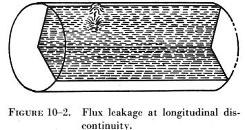
at a transverse discontinuity is shown in figure 10-1. The flux leakage
at a longitudinal discontinuity is shown in figure 10-2.
|
|
Types of Discontinuities Disclosed
The following types of discontinuities are normally detected by the magnetic particle test: cracks, laps, seams, cold shuts, inclusions, splits, tears, pipes, and voids. All these may affect the reliability of parts in service.
Cracks, splits, bursts, tears, seams, voids, and pipes are formed by an actual parting or rupture of the solid metal. Cold shuts and laps are folds that have been formed in the metal, interrupting its continuity.
Inclusions are foreign material formed by impurities in the metal during
the metal processing stages. They may consist, for example, of bits of
furnace lining picked up during the melting of the basic metal or of other
foreign constituents. Inclusions interrupt the continuity of the metal
because they prevent the joining or welding of adjacent faces of the metal.
Preparation of Parts for Testing
Grease, oil, and dirt must be cleaned from all parts before they are tested. Cleaning is very important, since any grease or other foreign material present can produce nonrelevant indications due to magnetic particles adhering to the foreign material as the suspension drains from the part.
Grease or foreign material in sufficient amount over a discontinuity may also prevent the formation of a pattern at the discontinuity. It is not advisable to depend upon the magnetic particle suspension to clean the part. Cleaning by suspension is not thorough, and any foreign materials so removed from the part will contaminate the suspension, thereby reducing its effectiveness.
In the dry procedure, thorough cleaning is absolutely necessary. Grease or other foreign material would hold the magnetic powder, resulting in nonrelevant indications and making it impossible to distribute the indicating medium evenly over the part's surface.
All small openings and oil holes leading to internal passages or cavities should be plugged with paraffin or other suitable nonabrasive material.
Coatings of cadmium, copper, tin, and zinc do not interfere with the satisfactory performance of magnetic particle inspection, unless the coatings are unusually heavy or the discontinuities to be detected are unusually small.
Chromium and nickel plating generally will not interfere with indications of cracks open to the surface of the base metal but will prevent indications of fine discontinuities, such as inclusions.
Because it is more strongly magnetic, nickel plating is more effective
than chromium plating in preventing the formation of indications.
| Effect of Flux Direction
In order to locate a defect in a part, it is essential that the magnetic lines of force pass approximately perpendicular to the defect. It is, therefore, necessary to induce magnetic flux in more than one direction, since defects are likely to exist at any angle to the major axis of the part. This requires two separate magnetizing operations, referred to as circular magnetization and longitudinal magnetization. The effect of flux direction is illustrated in figure 10-3. Circular magnetization is the inducing of a magnetic field, consisting of concentric circles of force about and within the part, by passing electric current through the part. This type of magnetization will locate defects running approximately parallel to the axis of the part. Circular magnetization of a part of solid cross section is illustrated in figure 10-4. Each head of the magnetizing unit is electrically connected to a pushbutton control, so that when contact is made the magnetizing current passes from one head to the other through the part. |
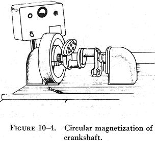 |
Figure 10-5 illustrates circular magnetization of a hollow part by passing the magnetizing current through a conductor bar located on the axis of the part.
In longitudinal magnetization the magnetic field is produced in a direction parallel to the long axis of the part. This is accomplished by placing the part in a solenoid excited by electric current. The metal part then becomes the core of an electromagnet and is magnetized by induction from the magnetic field created in the solenoid.
In longitudinal magnetization of long parts, the solenoid must be moved along the part in order to magnetize it. (See figure 10-6.) This is necessary to ensure adequate field strength throughout the entire length of the part.
Solenoids produce effective magnetization for approximately 12 inches from each end of the coil, thus accommodating parts or sections approximately 30 inches in length. Longitudinal magnetization equivalent to that obtained by a solenoid may be accomplished by wrapping a flexible electrical conductor around the part, as shown in figure 10-7. Although this method is not as convenient, it has the advantage that the coils conform more closely to the shape of the part, thus producing somewhat more uniform magnetization.
The flexible coil method is also useful for large or irregularly shaped parts for which standard solenoids are not available.
Effect of Flux Density
The effectiveness of the magnetic particle inspection also depends on the flux density or field strength at the surface of the part when the indicating medium is applied. As the flux density in the part is increased, the sensitivity of the test increases because of the greater flux leakages at discontinuities and the resulting improved formation of magnetic particle patterns.
Excessively high flux densities, however, may form nonrelevant indications; for example, patterns of the grain flow in the material. These indications will interfere with the detection of patterns resulting from significant discontinuities. It is therefore necessary to use a field strength high enough to reveal all possible harmful discontinuities, but not strong enough to produce confusing nonrelevant indications.
Magnetizing Methods
When a part is magnetized, the field strength in the part increases to a maximum for the particular magnetizing force and remains at this maximum as long as the magnetizing force is maintained.
When the magnetizing force is removed, the field strength decreases to a lower residual value depending on the magnetic properties of the material and the shape of the part. These magnetic characteristics determine whether the continuous or residual method is used in magnetizing the part.
In the continuous inspection method, the part is magnetized and the indicating medium applied while the magnetizing force is maintained. The available flux density in the part is thus at a maximum. The maximum value of flux depends directly upon the magnetizing force and the permeability of the material of which the part is made.
The continuous method may be used in practically all circular and longitudinal magnetization procedures. The continuous procedure provides greater sensitivity than the residual procedure, particularly in locating subsurface discontinuities. The highly critical nature of aircraft parts and assemblies and the necessity for subsurface inspection in many applications have resulted in the continuous method being more widely used.
Inasmuch as the continuous procedure will reveal more nonsignificant discontinuities than the residual procedure, careful and intelligent interpretation and evaluation of discontinuities revealed by this procedure are necessary.
The residual inspection procedure involves magnetization of the part and application of the indicating medium after the magnetizing force has been removed. This procedure relies on the residual or permanent magnetism in the part and is more practical than the continuous procedure when magnetization is accomplished by flexible coils wrapped around the part.
In general, the residual procedure is used only with steels which have been heat treated for stressed applications.
Identification of Indications
The correct evaluation of the character of indications is extremely important but is sometimes difficult to make from observation of the indications alone. The principal distinguishing features of indications are shape, buildup, width, and sharpness of outline. These characteristics, in general, are more valuable in distinguishing between types of discontinuities than in determining their severity. However, careful observation of the character of the magnetic particle pattern should always be included in the complete evaluation of the significance of an indicated discontinuity.
The most readily distinguished indications are those produced by cracks open to the surface. These discontinuities include fatigue cracks, heat treat cracks, shrink cracks in welds and castings, and grinding cracks.
Fatigue cracks give sharp, clear patterns, generally uniform and unbroken throughout their length and with good buildup. They are often jagged in appearance, as compared with the straight indications of a seam, and may also change direction slightly in localized areas. Figure 10-8 illustrates a fatigue crack.
Fatigue cracks are found in parts that have been in service but are never found in new parts. They are usually in highly stressed areas of the part or where a stress concentration exists for some reason. It is important to recognize that even a small fatigue crack indicates positively that failure of the involved parts is in progress.
Heat treat cracks have a smooth outline but are usually less clear and have less buildup than fatigue cracks. On thin sections, such as cylinder barrel walls, heat treat cracks may give very heavy patterns (figure 10-9). These heat treat cracks have a characteristic form, consisting of short jagged lines grouped together.
Shrink cracks give a sharp, clear pattern and the line is usually very jagged. Since the walls of shrink cracks are close together, their indications generally build up to less extent than do indications of fatigue cracks.
Grinding cracks are fine and sharp but seldom have a buildup because of their limited depth. Grinding cracks vary from single line indications to a heavy network of lines. Grinding cracks are generally related to the direction of grinding. For example, the crack usually begins and continues at right angles to the motion of a grinding wheel, giving a rather symmetrical pattern. Indications of grinding cracks can frequently be identified by means of this relation.
Indications of seams are usually straight, sharp, and fine. They are often intermittent and sometimes have very little buildup.
Hairlines are very fine seams in which the faces of the seam have been forced very close together during fabrication. Hairline indications are very fine and sharp, with very little buildup. Discontinuities of this type are normally considered detrimental only in highly stressed parts.
Inclusions are nonmetallic materials, such as slag materials and chemical compounds, that have been trapped in the solidifying ingot. They are usually elongated and strung out as the ingot is worked in subsequent processing operations.
Inclusions appear in parts in varying sizes and shapes, from stringers easily visible to the eye to particles only visible under magnification. In a finished part they may occur as either surface or subsurface discontinuities.
Indications of subsurface inclusions are usually broad and fuzzy. They are seldom continuous or of even width and density throughout their length. Larger inclusions, particularly those near or open to the surface, appear more clearly defined. Close examination, however, will generally reveal their lack of definition and the fact that the indication consists of several parallel lines rather than a single line. These characteristics will usually distinguish a heavy inclusion from a crack.
When cavities are located considerably below the surface of a part, the magnetic particle test is not a reliable method of detecting them. If any indication is obtained, it is likely to be an indistinct and inexact outline of the cavity, with the magnetic substance tending to distribute over the whole area rather than to outline clearly the boundary of the discontinuity. Defects of this type are detected more easily by radiographic procedures.
Laps may be identified by their form and location. They tend to occur at the ends or flash line of a forging. The indications are usually heavy and irregular. Islands and short branch indications usually break a lap indication of any length, and the scale included in the lap invariably gives fuzzy or small fernlike patterns stemming from the main indication.
When an ingot solidifies, the distribution of the various elements or compounds, generally, is not uniform throughout the mass of the ingot. Marked segregations of some constituents may thus occur. As the ingot is forged and then rolled, these segregations are elongated and reduced in cross section. Upon subsequent processing, they may appear as very thin parallel lines or bands, known as banding.
Segregation in the form of banding is sometimes revealed by magnetic particle inspection, particularly when high field strengths are used. Banding is not normally considered significant.
The most serious forms of segregation probably occur in castings. Here the basic condition of the metal remains unaltered in the finished part, and any segregations occur as they were originally formed. They may vary in size and will normally be irregular in shape. They may occur on or below the surface.
Magnaglo Inspection
Magnaglo inspection is similar to the preceding method, except that a fluorescent particle solution is used and the inspection is made under black light. Efficiency of inspection is increased by the neon-like glow of defects, and smaller flaw indications are more readily seen. This is an excellent method for use on gears, threaded parts, and aircraft engine components. The reddish brown liquid spray or bath that is used consists of Magnaglo paste mixed with a light oil at the ratio of 0.10 to 0.25 ounce of paste per gallon of oil.
After inspection, the part must be demagnetized and rinsed with a cleaning solvent.