MAGNETISM
MAGNETISM
Magnetism is so closely allied with electricity in the modern industrial
world it can be safely stated that without magnetism the electrical world
would not be possible. Knowledge of magnetism has existed for many centuries,
but it was not until the eighteenth century that this stream of knowledge
was joined with that of electricity by the discoveries of science.
The earliest known magnetism was the lodestone, a natural mineral found
in Asia Minor. Today this substance is called magnetite or magnetic oxide
of iron. When a piece of this ore is suspended horizontally by a thread
or floated on wood in undisturbed water, it will align itself in a north-south
direction. This characteristic led to its use as a compass and the name
lodestone, meaning leading stone. Other than the earth itself, the lodestone
is the only natural magnet. All other magnets are produced artificially.
From the earliest times a great deal was known about the elementary
behavior of magnets. For example, it was known that the property of magnetism
could be induced in an iron bar by stroking it with a lodestone. In addition,
it was known that if the north seeking end of a suspended magnet was brought
near the north seeking end of another, the magnets would repel each other.
On the other hand, they found that a north seeking and a south seeking
end would attract each other.
| Magnetism is defined as the property of an object to attract
certain metallic substances. In general, these substances are ferrous materials;
that is, materials composed of iron or iron alloys, such as soft iron,
steel, and alnico. These materials, sometimes called magnetic materials,
today include at least three nonferrous materials: nickel, cobalt and gadolinium,
which are magnetic to a limited degree. All other substances are considered
nonmagnetic, and a few of these nonmagnetic substances can be classified
as diamagnetic since they are repelled by both poles of a magnet.
Magnetism is an invisible force, the ultimate nature of which has not
been fully determined.
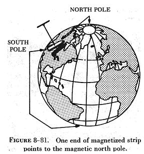
It can best be described by the effects it produces. Examination of
a simple bar magnet similar to that illustrated in figure 8-81 discloses
some basic characteristics of all magnets. If the magnet is suspended to
swing freely, it will align itself with the earth's magnetic poles. One
end is labelled "N," meaning the north seeking end or pole of the magnet.
If the "N" end of a compass or magnet is referred to as north seeking rather
than north, there will be no conflict in referring to the pole it seeks,
which is the north magnetic pole. The opposite end of the magnet, marked
"S" is the south seeking end and points to the south magnetic pole. Since
the earth is a giant magnet, its poles attract the ends of the magnet.
These poles are not located at the geographic poles. |
|
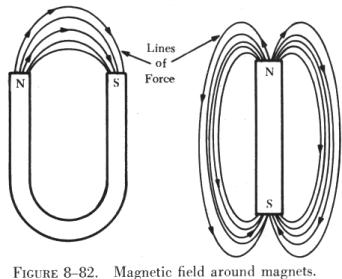 |
The somewhat mysterious and completely invisible force of a magnet
depends on a magnetic field that surrounds the magnet as illustrated in
figure 8-82. This field always exists between the poles of a magnet, and
will arrange itself to conform to the shape of any magnet.
The theory that explains the action of a magnet holds that each molecule
making up the iron bar is itself a tiny magnet, with both north and south
poles as illustrated in A of figure 8-83. These molecular magnets each
possess a magnetic field, but in an unmagnetized state the molecules are
arranged at random throughout the iron bar. If a magnetizing force, such
as stroking with a lodestone, is applied to the unmagnetized bar, the molecular
magnets rearrange themselves in line with the magnetic field of the lodestone,
with all north ends of the magnets pointing in one direction and all south
ends in the opposite direction. This is illustrated in B of figure
8-83. In such a configuration, the magnetic fields of the magnets combined
to produce the total field of the magnetized bar. |
| When handling a magnet, avoid applying direct heat, or
hammering or dropping it. Heating or sudden shock will cause misalignment
of the molecules, causing the strength of a magnet to decrease. When a
magnet is to be stored, devices known as "keeper bars" are installed to
provide an easy path for flux lines from one pole to the other. This promotes
the retention of the molecules in their north-south alignment.
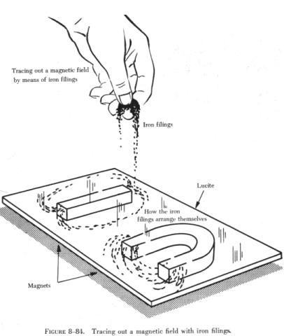
The presence of the magnetic force or field around a magnet can best
be demonstrated by the experiment illustrated in figure 8-84. A sheet of
transparent material such as glass or lucite is placed over a bar magnet
and iron filings are sprinkled slowly on this transparent shield. If the
glass or lucite is tapped lightly, the iron filings will arrange themselves
in a definite pattern around the bar, forming a series of lines from the
north to south end of the bar to indicate the pattern of the magnetic field.
As shown, the field of a magnet is made up of many individual forces
that appear as lines in the iron filing demonstration. Although they are
not "lines" in the ordinary sense, this word is used to describe the individual
nature of the separate forces making up the entire magnetic field. These
lines of force are also referred to as magnetic flux. |
|
They are separate and individual forces, since one line will never cross
another; indeed, they actually repel one another. They remain parallel
to one another and resemble stretched rubber bands, since they are held
in place around the bar by the internal magnetizing force of the magnet.
The demonstration with iron filings further shows that the magnetic
field of a magnet is concentrated at the ends of the magnet. These areas
of concentrated flux are called the north and south poles of the magnet.
There is a limit to the number of lines of force that can be crowded into
a magnet of a given size. When a magnetizing force is applied to a piece
of magnetic material, a point is reached where no more lines of force can
be induced or introduced. The material is then said to be saturated.
The characteristics of the magnetic flux can be demonstrated by tracing
the flux patterns of two bar magnets with like poles together, as shown
in figure 8-85. The two like poles repel one another
because the lines of force will not cross each other. As the arrows on
the individual lines indicate, the lines turn aside as the two like poles
are brought near each other and travel in a path parallel to each other.
Lines moving in this manner repel each other, causing the magnets as a
whole to repel each other.
By reversing the position of one of the magnets, the attraction of unlike
poles can be demonstrated, as shown in figure 8-86.
As the unlike poles are brought near each other, the lines of force
rearrange their paths and most of the flux leaving the north pole of one
magnet enters the south pole of the other. The tendency of lines of force
to repel each other is indicated by the bulging of the flux in the air
gap between the two magnets.
To further demonstrate that lines of force will not cross one another,
a bar magnet and a horseshoe magnet can be positioned to display a magnetic
field similar to that of figure 8-87. The magnetic
fields of the two magnets do not combine, but are rearranged into a distorted
flux pattern.
The two bar magnets may be held in the hands and the north poles brought
near each other to demonstrate the force of repulsion between like poles.
In a similar manner the two south poles can demonstrate this force. The
force of attraction between unlike poles can be felt by bringing a south
and a north end together, These experiments are illustrated in figure 8-88.
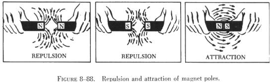
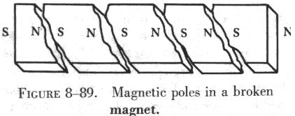
Figure 8-89 illustrates another characteristic of magnets. If the bar
magnet is cut or broken into pieces, each piece immediately becomes a magnet
itself, with a north and south pole. This feature supports the theory that
each molecule is a magnet, since each successive division of the magnet
produces still more magnets.
Since the magnetic lines of force form a continuous loop, they form
a magnetic circuit. It is impossible to say where in the magnet they originate
or start. Arbitrarily, it is assumed that all lines of force leave the
north pole of any magnet and enter at the south pole.
There is no known insulator for magnetic flux, or lines of force, since
they will pass through all materials. However, it has been found that they
will pass through some materials more easily than others.
Thus, it is possible to shield certain areas, such as instruments, from
the effects of the flux by surrounding them with a material that offers
an easier path for the lines of force. Figure 8-90
shows an instrument surrounded by a path of soft iron, which offers very
little opposition to magnetic flux. The lines of force take the easier
path, the path of greater permeability, and are guided away from the instrument.
Materials, such as soft iron and other ferrous metals, are said to have
a high permeability, the measure of the ease with which magnetic flux can
penetrate a material. The permeability scale is based on a perfect vacuum
with a rating of one. Air and other nonmagnetic materials are so close
to this that they are also considered to have a rating of one. The nonferrous
metals having a permeability greater than one, such as nickel and cobalt,
are called paramagnetic, while the term ferromagnetic is applied to iron
and its alloys, which have by far the greatest permeability. Any substance,
such as bismuth, having a permeability of less than one, is considered
diamagnetic.
Reluctance, the measure of opposition to the lines of force through
a material, can be compared to the resistance of an electrical circuit.
The reluctance of soft iron, for instance, is much lower than that of air.
Figure 8-91 demonstrates that a piece of soft iron
placed near the field of a magnet can distort the lines of force, which
follow the path of lowest reluctance through the soft iron.
The magnetic circuit can be compared in many respects to an electrical
circuit. The magnetomotive force (m.m.f.), causing lines of force in the
magnetic circuit, can be compared to the electromotive force or electrical
pressure of an electrical circuit. The m.m.f. is measured in gilberts,
symbolized by the capital letter "F." The symbol for the intensity of the
lines of force, or flux, is the Greek letter phi, and the unit of field
intensity is the gauss. An individual line of force, called a maxwell,
in an area of one square centimeter produces a field intensity of one gauss.
Using reluctance rather than permeability, the law for magnetic circuits
can be stated: A magnetomotive force of one gilbert will cause one maxwell,
or line of force, to be set up in a material when the reluctance of the
material is one.
Types of Magnets
Magnets are either natural or artificial. Since naturally occurring
magnets or lodestones have no practical use, all magnets considered in
this study are artificial or man made. Artificial magnets can be further
classified as permanent magnets, which retain their magnetism long after
the magnetizing force has been removed, and temporary magnets, which quickly
lose most of their magnetism when the external magnetizing force is removed.
Hard steel has long been used to make permanent magnets, but magnets
of even better quality are now available from various alloys. Alnico, an
alloy of iron, aluminum, nickel and cobalt, is considered one of the very
best. Others with excellent magnetic qualities are alloys such as Remalloy
and Permendur.
The old method of producing a magnet by stroking a piece of steel or
iron with a natural magnet has been replaced by other means. A piece of
metal placed in contact with, or even near, a magnet will become magnetized
by induction and the process can be accelerated by heating the metal and
then placing it in a magnetic field to cool. Magnets can also be produced
by placing the metal to be magnetized in a strong magnetic field and striking
it several times with a hammer, This process can be used to produce permanent
magnets from metals such as hard steel.
The ability of a magnet to hold its magnetism varies greatly with the
type of metal and is known as retentivity. Magnets made of soft iron are
very easily magnetized but quickly lose most of their magnetism when the
external magnetizing force is removed. The small amount of magnetism remaining,
called residual magnetism, is of great importance in such electrical applications
as generator operation.
Horseshoe magnets are commonly manufactured in two forms, as shown in
figure 8-92. The most common type is made from a
long bar curved into a horseshoe shape, while a variation of this type
consists of two bars connected by a third bar, or yoke.
Magnets can be made in many different shapes, such as balls, cylinders,
or disks. One special type of magnet is the ring magnet, or Gramme ring,
often used in instruments. This is a closed loop magnet, similar to the
type used in transformer cores, and is the only type that has no poles.
Sometimes special applications require that the field of force lie through
the thickness rather than the length of a piece of metal. Such magnets
are called flat magnets and are used as pole pieces in generators and motors.
Electromagnetism
In 1819, the Danish physicist, Hans Christian Oersted, discovered that
the needle of a compass brought near a current carrying conductor would
be deflected. When the current flow stopped, the compass needle returned
to its original position. This important discovery demonstrated a relationship
between electricity and magnetism that led to the electromagnet and to
many of the inventions on which modern industry is based.
Oersted discovered that the magnetic field had no connection with the
conductor in which the electrons were flowing, because the conductor was
made of nonmagnetic copper. The magnetic field around the conductor was
created by the electrons moving through the wire. Since a magnetic field
accompanies a charged particle, the greater the current flow the greater
the magnetic field. Figure 8-93 illustrates the
magnetic field around a current carrying wire. A series of concentric circles
around the conductor represent the field, which, if all the lines were
shown, would appear more as a continuous cylinder of such circles around
the conductor.
As long as current flows in the conductor, the lines of force remain
around it, as shown in figure 8-94. If a small current
flows through the conductor, there will be a line of force extending out
to circle A. If the current flow is increased, the line of force will increase
in size to circle B, and a further increase in current will expand it to
circle C. As the original line (circle) of force expands from circle A
to B, a new line of force will appear at circle A. As the current flow
increases, the number of circles of force increases, expanding the outer
circles farther from the surface of the current carrying conductor.
If the current flow is a steady nonvarying direct current, the magnetic
field remains stationary. When the current stops, the magnetic field collapses
and the magnetism around the conductor disappears.
A compass needle is used to demonstrate the direction of the magnetic
field around a current carrying conductor. A of figure
8-95 shows a compass needle positioned at right angles to, and approximately
one inch from, a current carrying conductor. If no current were flowing,
the north seeking end of the compass needle would point toward the earth's
magnetic pole. When current flows, the needle lines itself up at right
angles to a radius drawn from the conductor. Since the compass needle is
a small magnet, with lines of force extending from south to north inside
the metal, it will turn until the direction of these lines agrees with
the direction of the lines of force around the conductor. As the compass
needle is moved around the conductor, it will maintain itself in a position
at right angles to the conductor, indicating that the magnetic field around
a current carrying conductor is circular. As shown in B of figure
8-95, when the direction of current flow through the conductor is reversed,
the compass needle will point in the opposite direction, indicating the
magnetic field has reversed its direction.
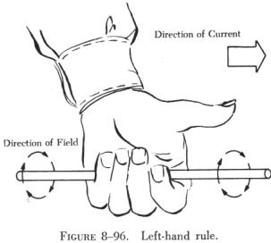
| A method used to determine the direction of the lines of
force when the direction of the current flow is known, is shown in figure
8-96. If the conductor is grasped in the left hand, with the thumb pointing
in the direction of current flow, the fingers will be wrapped around the
conductor in the same direction as the lines of the magnetic field. This
is called the left-hand rule.
Although it has been stated that the lines of force have direction,
this should not be construed to mean that the lines have motion in a circular
direction around the conductor. Although the lines of force tend to act
in a clockwise or counterclockwise direction they are not revolving around
the conductor.
Since current flows from negative to positive, many illustrations indicate
current direction with a dot symbol on the end of the conductor when the
electrons are flowing toward and a plus sign when the current is flowing
away from the observer. This is illustrated in figure
8-97. |
|
When a wire is bent into a loop and an electric current flows through
it, the left-hand rule remains valid, as shown in figure
8-98.
If the wire is coiled into two loops, many of the lines of force become
large enough to include both loops. Lines of force go through the loops
in the same direction, circle around the outside of the two coils, and
come in at the opposite end. (See figure 8-99.)
When a wire contains many such loops, it is called a coil. The lines
of force form a pattern through all the loops, causing a high concentration
of flux lines through the center of the coil. (See figure
8-100.)
In a coil made from loops of a conductor, many of the lines of force
are dissipated between the loops of the coil. By placing a soft iron bar
inside the coil, the lines of force will be concentrated in the center
of the coil, since soft iron has a greater permeability than air. (See
figure 8-101.) This combination of an iron core
in a coil of wire loops, or turns, is called an electromagnet, since the
poles (ends) of the coil possess the characteristics of a bar magnet.
The addition of the soft iron core does two things for the current carrying
coil. First, the magnetic flux is increased, and second, the flux lines
are more highly concentrated.
| When direct current flows through the coil, the core will become magnetized
with the same polarity (location of north and south poles) as the coil
would have without the core. If the current is reversed, the polarity will
also be reversed.
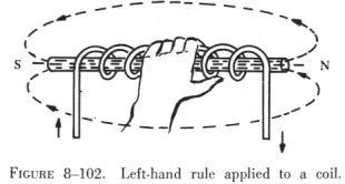
The polarity of the electromagnet is determined by the left-hand rule
in the same manner as the polarity of the coil without the core was determined.
If the coil is grasped in the left hand in such a manner that the fingers
curve around the coil in the direction of electron flow (minus to plus),
the thumb will point in the direction of the north pole. (See figure 8-102.) |
|
The strength of the magnetic field of the electromagnet can be increased
by either increasing the flow of current or the number of loops in the
wire. Doubling the current flow approximately doubles the strength of the
field, and in a similar manner, doubling the number of loops approximately
doubles magnetic field strength. Finally, the type metal in the core is
a factor in the field strength of the electromagnet.
 |
A soft iron bar is attracted to either pole of a permanent magnet and,
likewise, is attracted by a current carrying coil. As shown in figure 8-103,
the lines of force extend through the soft iron, magnetizing it by induction
and pulling the iron bar toward the coil. If the bar is free to move, it
will be drawn into the coil to a position near the center where the field
is strongest.
Electromagnets are used in electrical instruments, motors, generators,
relays, and other devices. Some electromagnetic devices operate on the
principle that an iron core held away from the center of a coil will be
rapidly pulled into a center position when the coil is energized. This
principle is used in the solenoid, also called solenoid switch or relay,
in which the iron core is springloaded off center and moves to complete
a circuit when the coil is energized. |
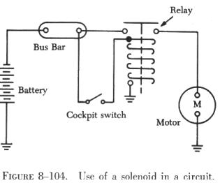
| The application of the solenoid is shown in figure 8-104,
where it is a solenoid relay. When the cockpit switch is closed, the energized
coil pulls the core switch down, which completes the circuit to the motor.
Since this solenoid relay operates on low current, it eliminates high amperage
wiring in the cockpit of the aircraft.
The solenoid and plunger type of magnet in various forms is used extensively
to open circuit breakers automatically, when the load current becomes excessive,
and to operate valves, magnetic brakes, and many other devices. The armature-type
of electromagnet also has extensive applications. For this type of magnet,
the coil is wound on and insulated from the iron core; the core is not
movable. When current flows through the coil, the iron core becomes magnetized
and causes a pivoted soft iron armature located near the electromagnet
to be attracted to it. These magnets are used in doorbells, relays, circuit
breakers, telephone receivers, and many other devices. |
|