METHODSOFILLUSTRATINGOBJECTS
METHODS OF ILLUSTRATING OBJECTS
A number of methods are used to illustrate objects graphically. The
most common are pictorial drawings, orthographic projections, and diagrams.
Pictorial Drawings
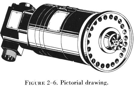 |
A pictorial drawing, figure 2-6, is similar to a photograph. It shows
an object as it appears to the eye, but it is not satisfactory for showing
complex forms and shapes. Pictorial drawings are useful in showing the
general appearance of an object and are used extensively with orthographic
projection drawings. Pictorial drawings are used in maintenance, overhaul,
and part numbers.
Orthographic Projection Drawings
In order to show the exact size and shape of all the parts of complex
objects, a number of views are necessary. This is the system used in orthographic
projection. In orthographic projection there are six possible views of
an object, because all objects have six sides - front, top, bottom, rear,
right side, and left side. |
| Figure 2-7(a) shows an object placed
in a transparent box, hinged at the edges. The projections on the sides
of the box are the views as seen looking straight at the object through
each side. If the outlines of the object are drawn on each surface and
the box opened as shown in 2-7(b), then laid flat
as shown in 2-7(c), the result is a six view orthographic
projection.
It is seldom necessary to show all six views to portray an object clearly;
therefore, only those views necessary to illustrate the required characteristics
of the object are drawn. One view, two view, and three view drawings are
the most common. Regardless of the number of views used, the arrangement
is generally as shown in figure 2-7, with the front
view being the principal one. If the right side view is shown, it will
be to the right of the front view. If the left side view is shown, it will
be to the left of the front view. The top and bottom views, if included,
will be shown in their respective positions relative to the front view. |
|
 |
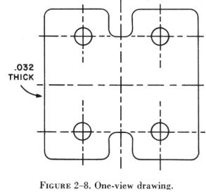
One view drawings are commonly used for objects of uniform thickness,
such as gaskets, shims, and plates. A dimensional note gives the thickness
as shown in figure 2-8. One view drawings are also commonly used for cylindrical,
spherical, or square parts if all the necessary dimensions can be properly
shown in one view.
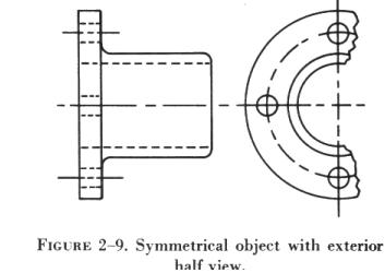
When space is limited and two views must be shown, symmetrical objects
are often represented by half views, as illustrated in figure 2-9.
Aircraft drawings seldom show more than two principal, or complete,
views of an object. Instead, generally there will be one complete view
and one or more detail views or sectional views. |
Detail View
A detail view shows only a part of the object but in greater detail
and to a larger scale than the principal view. The part that is shown in
detail elsewhere on the drawing is usually encircled by a heavy line on
the principal view. Figure 2-10 is an example of
the use of detail views.
The principal view shows the complete control wheel, while the detail
view is an enlarged drawing of a portion of the control wheel.
Sectional Views
A section or sectional view is obtained by cutting away part of an object
to show the shape and construction at the cutting plane. The part or parts
cut away are shown by the use of section (crosshatching) lines.
Sectional views are used when the interior construction or hidden features
of an object cannot be shown clearly by exterior views. For example, figure
2-11, a sectional view of a coaxial cable connector, shows the internal
construction of the connector. This is known as a full section. Other types
of sections are described in the following paragraphs.
Half Sections
In a half section, the cutting plane extends only halfway across the
object, leaving the other half of the object as an exterior view.
Half sections are used to advantage with symmetrical objects to show
both the interior and exterior. Figure 2-12 is a
half sectional view of a quick disconnect used in aircraft fluid systems.
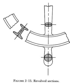
Revolved Sections
A revolved section drawn directly on the exterior view shows the shape
of the cross section of a part, such as the spoke of a wheel. An example
of a revolved section is shown in figure 2-13.
Removed Sections
Removed sections illustrate particular parts of an object. They are
drawn like revolved sections, except that they are placed at one side and,
to bring out pertinent details, are often drawn to a larger scale than
the view on which they are indicated. |
|
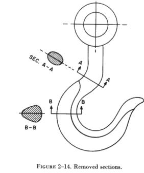 |
Figure 2-14 is an illustration of removed sections. Section A-A shows
the cross-sectional shape of the object at cutting plane line A-A. Section
B-B shows the cross-sectional shape at cutting plane line B-B. These sectional
views are drawn to the same scale as the principal view; however, as already
mentioned, they are often drawn to a larger scale to bring out pertinent
details.
|