MULTIMETERS
| MULTIMETERS
Ammeters are commonly incorporated in multiple purpose instruments such
as multimeter or volt-ohm-milliammeters. These instruments vary somewhat
according to the design used by different manufacturers, but most incorporate
the functions of an ammeter, a voltmeter, and an ohmmeter in one unit.
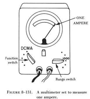
A typical multimeter is shown in figure 8-131.
This multimeter has two selector switches: a function switch and a range
switch. Since a multimeter is actually three meters in one case, the function
switch must be placed in proper position for the type of measurement to
be made. In figure 8-131, the function switch is shown in the ammeter position
to measure dc milliamperes and the range switch is set at 1000. Set in
this manner, the ammeter can measure up to 1,000 milliamperes or 1 ampere. |
|
 |
Multimeters have several scales, and the one used should correspond
properly to the position of the range switch. If current of unknown value
is to be measured, always select the highest possible range to avoid damage
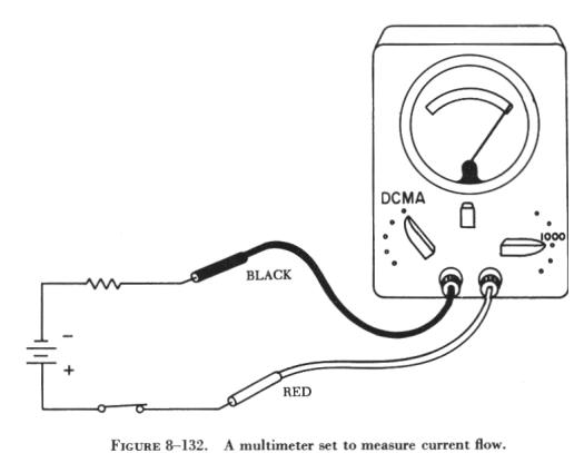
to the meter. The test leads should always be connected to the meter in
the manner prescribed by the manufacturer. Usually the red lead is positive
and the black lead is negative, or common. Many multimeters employ color
coded jacks as an aid in connecting the meter into the circuit to be tested.
In figure 8-132, a multimeter properly set to measure current flow is connected
into a circuit.
The precautions to be observed when using an ammeter are summarized
as follows: |
1. Always connect an ammeter in series with the element through which
the current flow is to be measured.
2. Never connect an ammeter across a source of voltage, such as a battery
or generator. Remember that the resistance of an ammeter, particularly
on the higher ranges, is extremely low and that any voltage, even a volt
or so, can cause very high current to flow through the meter, causing damage
to it.
3. Use a range large enough to keep the deflection less than full scale.
Before measuring a current, form some idea of its magnitude. Then switch
to a large enough scale or start with the highest range and work down until
the appropriate scale is reached. The most accurate readings are obtained
at approximately half scale deflection. Many milliammeters have been ruined
by attempts to measure amperes. Therefore, be sure to read the lettering
either on the dial or on the switch positions and choose proper scale before
connecting the meter in the circuit.
4. Observe proper polarity in connecting the meter in the circuit. Current
must flow through the coil in a definite direction in order to move the
indicator needle up scale. Current reversal because of incorrect connection
in the circuit results in a reversed meter deflection and frequently causes
bending of the meter needle. Avoid improper meter connections by observing
the polarity markings on the meter.