The most important law applicable to the study of electricity is Ohm's law. This law, which outlines the relationship between voltage, current, and resistance in an electrical circuit, was first stated by the German physicist, George Simon Ohm (1787 - 1854). This law applies to all direct current circuits. In a modified form it may be applied to the alternating circuits to be studied later in this text. Ohm's experiments showed that current flow in an electrical circuit is directly proportional to the amount of voltage applied to the circuit. Stated in different words, this law says that as the voltage increases, the current increases; and when the voltage decreases, the current flow decreases. It should be added that this relationship is true only if the resistance in the circuit remains constant. For it can be readily seen that if the resistance changes, current also changes.
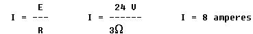
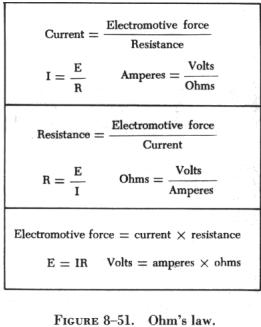
| Ohm's law may be expressed as an equation, as follows: |
| Where I is current in amperes, E is the potential
difference measured in volts, and R is the resistance measured in
ohms (designated by the Greek letter omega, whose symbol is |
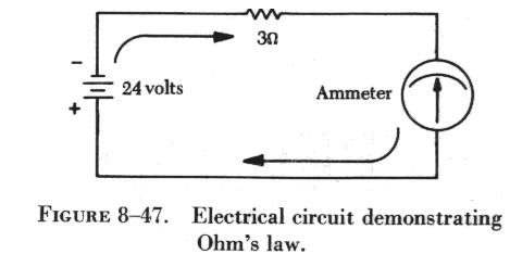 |
Some features of figure 8-47 that are typical of all electrical circuits
drawn in schematic form should be reviewed. The electrical pressure or
potential difference applied to the circuit is represented in schematic
form by the symbol for a battery. The negative sign is located near one
side to indicate the negative terminal of the source, or battery. The opposite
side is marked positive with a + symbol. Arrows are sometimes used to indicate
the direction of current flow from the negative terminal, through the conducting
wires and other circuit devices, to the positive terminal of the source.
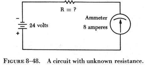
| Figure 8-48 shows that the values of voltage and current
are known. To find the quantity of resistance in the circuit, Ohm's law
can be transposed to solve for R.
Transposing the basic formula I = E/R to R = E/I, and substituting the
known circuit values in the equation, R = 24 volts/8 amperes = 3 ohms,
or 3 |
 |
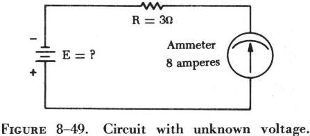 |
Ohm's law can also be transposed to determine the voltage applied to
a circuit when current flow and resistance are known, as shown in figure
8-49.
In this circuit the unknown circuit quantity, the voltage, is represented by the symbol E. The value of resistance is 3 ohms, and the current flow is 8 amperes. (The word amperes is often shortened to "amps.") Transposing Ohm's law from its basic formula, the equation to solve for E becomes E = I x R. |
Substituting the known values in the equation,
E = 8 x 3
E = 24 volts or 24 V
The relationship between the various circuit quantities can be further
demonstrated if the resistance in a circuit is held constant. In such a
case, the current will increase or decrease in direct proportion to the
increase or decrease of voltage applied to the circuit. For example, if
the voltage applied to a circuit is 120 volts and the resistance of the
circuit is 20 ohms, the current flow will be 120/20, or 6 amperes. If this
resistance remains constant at 20 ohms, a graph of voltage-current relationship,
as shown in figure 8-50, can be plotted.
| The relationship between voltage and current in this example
shows voltage plotted horizontally along the X axis in values from 0 to
120 volts, and the corresponding values of current are plotted vertically
in values from 0 to 6.0 amperes along the Y axis. A straight line drawn
through all the points where the voltage and current lines meet represents
the equation I = E/20 and is called a linear relationship.
The constant, 20, represents the resistance, which is assumed not to change in this example. This graph represents an important characteristic of the basic law, that the current varies directly with the applied voltage if the resistance remains constant. The basic equations derived from Ohm's law are summarized, together with the units of measurements of circuit quantities, in figure 8-51. |
 |
 |
 |
 |
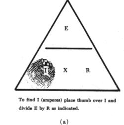
The various equations which may be derived by transposing the basic law can be easily obtained by using the triangles in figure 8-52.
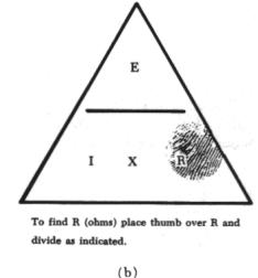
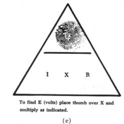
The triangles containing E, I, and R are divided into two parts, with E above the line and I x R below it. To determine an unknown circuit quantity when the other two are known, cover the unknown quantity with a thumb. The location of the remaining uncovered letters in the triangle will indicate the mathematical operation to be performed. For example, to find I, refer to (a) of figure 8-52, and cover I with the thumb. The uncovered letters indicate that E is to be divided by R, or I = E/R. To find R, refer to (b) of figure 8-52, and cover R with the thumb. The result indicates that E is to be divided by I, or R = E/I. To find E, refer to (c) of figure 8-52, and cover E with the thumb. The result indicates I is to be multiplied by R, or E = I x R.
This chart is useful when learning to use Ohm's law. It should be used to supplement the beginner's knowledge of the algebraic method.
Power
In addition to the volt, ampere, and ohm, there is one other unit frequently used in electrical circuit calculations. This is the unit of power. The unit used to measure power in dc electrical circuits is the watt. Power is defined as the rate of doing work and is equal to the product of the voltage and current in a dc circuit. When the current in amperes (I) is multiplied by e.m.f in volts (E), the result is power measured in watts (P). This indicates that the electrical power delivered to a circuit varies directly with the applied voltage and current flowing in the circuit. Expressed as an equation, this becomes
P = IE
This equation may be transposed to determine any one of the three circuit quantities as long as the other two are known. Thus, if the power is read directly from a wattmeter and the voltage is measured with a voltmeter, the intensity of the current (I) flowing in the circuit can be determined by transposing the basic equation to I = P/E. Similarly, the voltage (E) can be found by transposing the basic power formula to E = P/I.
Since some of the values used to determine the power delivered to a circuit are the same as those used in Ohm's law, it is possible to substitute Ohm's law values for equivalents in the power formula.
In Ohm's law, I = E/R. If this value E/R is substituted for I in the power formula, it becomes
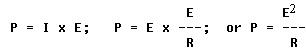
This equation, P = E2/R, illustrates that the power in watts delivered to a circuit varies directly with the square of the applied voltage and inversely with the circuit resistance.
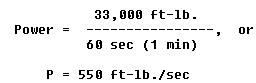
The watt is named for James Watt, the inventor of the steam engine. Watt devised an experiment to measure the power of a horse in order to find a means of measuring the mechanical power of his steam engine. One horsepower is required to move 33,000 pounds 1 foot in 1 minute. Since power is the rate of doing work, it is equivalent to the work divided by time. Stated as a formula, this is
Electrical power can be rated in a similar manner. For example, an electric motor rated as a 1 horsepower motor requires 746 watts of electrical energy. But the watt is a relatively small unit of power. Much more common is the kilowatt or 1,000 watts. (The prefix kilo means 1,000.) In measuring amounts of electrical energy consumed, the kilowatt hour is used. For example, if a 100 watt bulb consumes electrical energy for 20 hours, it has used 2,000 watt hours or 2 kilowatt hours of electrical energy.
Electrical power that is lost in the form of heat when current flows through an electrical device is often referred to as power loss. This heat is usually dissipated into the surrounding air and serves no useful purpose, except when used for heating. Since all conductors possess some resistance, circuits are designed to reduce these losses. Referring again to the basic power formula, P = I x E, it is possible to substitute the Ohm's law values for E in the power formula to obtain a power formula that directly reflects the power losses in a resistance.
P = I x E; E = I x R.
Substituting the Ohm's law value for E (I x R) in the power formula,
P = I x I x R.
Collecting terms, this gives,
![]()
From this equation, it can be seen that the power in watts in a circuit varies as the square of the circuit current in amperes and varies directly with the circuit resistance in ohms.
Finally, the power delivered to a circuit can be expressed as a function
of current and resistance by transposing the power equation ![]()
Transposing to solve for current gives

and by extracting the square root of both sides of the equation,
I = square root of P/R
Thus, the current through a 500 watt, 100 ohm load (resistance) is as follows:
I = the square root of P/R = 500/100 = 2.24 amperes.
The electrical equations derived from Ohm's law and the basic power formula do not reveal all about the behavior of circuits. They do indicate the numerical relation between the volt, ampere, ohm, and watt. Figure 8-53 provides a summary of all the possible transpositions of these formulas in a 12 segment circle.