OHMMETERS
OHMMETERS
Two instruments are commonly used to check the continuity or to measure
the resistance of a circuit or circuit element. These instruments are the
ohmmeter and the megger, or megohmmeter. The ohmmeter is widely used to
measure resistance and to check the continuity of electrical circuits and
devices. Its range usually extends to a few megohms.
| The megger is widely used for measuring insulation resistance,
such as the resistance between the windings and the frame of electric machinery,
and for measuring the insulation resistance of cables, insulators, and
bushings. Its range may extend to more than 1,000 megohms. When measuring
very high resistances of this nature, it is not necessary to find the exact
value of resistance, but rather to know that the insulation is either above
or below a certain standard. When precision measurements are required,
some type of bridge circuit is used. Ohmmeters may be of the series or
shunt type.
Series-type Ohmmeters
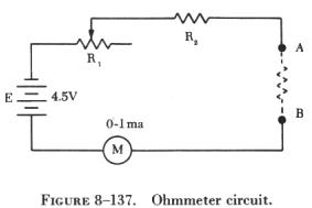
A simplified schematic of an ohmmeter is shown in figure 8-137. E is
a source of EMF; R1 is a variable resistor used to zero the meter; R2 is
a fixed resistor used to limit the current in the meter movement; and A
and B are test terminals across which the resistance to be measured is
placed. |
|
 |
If A and B are connected together (short circuited), the meter, the
battery, and resistors R1 and R2 form a simple series circuit. With R1
adjusted so that the total resistance in the circuit is 4,500 ohms, the
current through the meter is 1 ma. and the needle deflects full scale.
Since there is no resistance between A and B, this position of the needle
is labeled zero (figure 8-138). If a resistance equal to 4,500 ohms is
placed between terminals A and B, the total resistance is 9,000 ohms and
the current is 0.5 ma.
This causes the needle to deflect half scale. This half scale reading,
labeled 4.5 K ohms, is equal to the internal resistance of the meter, in
this instance 4,500 ohms. If a resistance of 9,000 ohms is placed between
terminals A and B, the needle deflects one-third scale. Resistances of
13.5 K and 1.5 K placed between terminals A and B will cause a deflection
of one-fourth and three-fourths scale, respectively. |
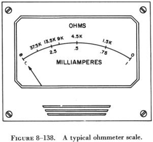
If terminals A and B are not connected (open circuited), no current
flows and the needle does not move. The left side of the scale is, therefore,
labeled infinity to indicate an infinite resistance.
A typical ohmmeter scale is shown in figure 8-138. Note that the scale
is not linear and is crowded at the high resistance end. For this reason,
it is good practice to use an ohmmeter range in which the readings are
not too far from mid scale. A good rule is to use a range in which the
reading obtained does not exceed ten times, or is not less than one-tenth,
the mid scale reading. The useful range of the scale shown is, by this
rule, from 450 ohms to 45,000 ohms.
Most ohmmeters have more than one scale. Additional scales are made
possible by using various values of limiting resistors and battery voltages.
Some ohmmeters have a special scale called a low ohm scale for reading
low resistances. A shunt-type ohmmeter circuit is used for this scale.
Shunt-Type Ohmmeter
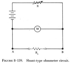
| Shunt-type ohmmeters are used to measure small values of
resistance. In the circuit shown in figure 8-139, E (voltage) is applied
across a limiting resistor R and a meter movement in series. Resistance
and battery values are chosen so that the meter movement deflects full
scale when terminals A and B are open. When the terminals are short circuited,
the meter reads zero; the short circuit conducts all the current around
the meter. The unknown resistance Rx is placed between terminals A and
B in parallel with the meter movement. The smaller the resistance value
being measured, the less current flows through the meter movement.
The value of the limiting resistor R is usually made large compared
to the resistance of the meter movement. This keeps the current drawn from
the battery practically constant. Thus, the value of Rx determines how
much of this constant current flows through the meter and how much through
Rx. |
|
Note that in a shunt-type ohmmeter, current is always flowing from the
battery through the meter movement and the limiting resistor. Therefore,
when using an ohmmeter with a low ohm scale, do not leave the switch in
low ohm position.
Use of the Ohmmeter
The ohmmeter is not as accurate a measuring device as the ammeter or
the voltmeter because of the associated circuitry. Thus, resistance values
cannot be read with greater than 5 to 10 percent accuracy. While there
are instruments which read the resistance of an element with very great
accuracy, they usually are more complicated to use.
In addition to measuring the resistance, the ohmmeter is a very useful
instrument for checking continuity in a circuit. Often, when troubleshooting
electronic circuits or wiring a circuit, visual inspections of all parts
of the current path cannot be readily accomplished. Therefore, it is not
always apparent whether a circuit is complete or whether current might
be flowing in the wrong part of the circuit because of contact with adjacent
circuits. The best method of checking a circuit under these conditions
is to send a current through the circuit. The ohmmeter is the ideal instrument
for checking circuits in this manner. It provides the power and the meter
to indicate whether the current is flowing.
Observe the following precautions when using an ohmmeter:
(1) Choose a scale which will contain the resistance of the element
to be measured. In general, use a scale in which the reading will fall
in the upper half of the scale (near full scale deflection).
(2) Short the leads together and set the meter to read zero ohms by
setting the zero adjustment. If the scale is changed, readjust to zero
ohms.
(3) Connect the unknown resistance between the test leads and read its
resistance from the scale. Never attempt to measure resistance in a circuit
while it is connected to a source of voltage. Disconnect at least one end
of the element being measured to avoid reading the resistance of parallel
paths.
Megger (Megohmmeter)
The megger, or megohmmeter, is a high range ohmmeter containing a hand
operated generator. It is used to measure insulation resistance and other
high resistance values. It is also used for ground, continuity, and short
circuit testing of electrical power systems. The chief advantage of the
megger over an ohmmeter is its capacity to measure resistance with a high
potential, or "breakdown" voltage. This type of testing ensures that insulation
or a dielectric material will not short or leak under potential electrical
stress.
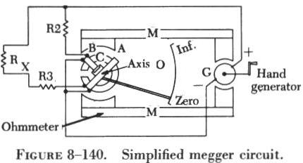
| The megger (figure 8-140) consists of two primary elements,
both of which are provided with individual magnetic fields from a common
permanent magnet: (1) A hand driven dc generator, G, which supplies the
necessary current for making the measurement and (2) the instrument portion,
which indicates the value of the resistance being measured. The instrument
portion is of the opposed coil type. Coils A and B are mounted on the movable
member with a fixed angular relationship to each other and are free to
turn as a unit in a magnetic field. Coil B tends to move the pointer counterclockwise
and coil A, clockwise. The coils are mounted on a light, movable frame
that is pivoted in jewel bearings and free to move about axis 0. |
|
Coil A is connected in series with R3 and the unknown resistance, Rx,
to be measured. The series combination of coil A, R3, and Rx is connected
between the + and - brushes of the dc generator. Coil B is connected in
series with R2 and this combination is also connected across the generator.
There are no restraining springs on the movable member of the instrument
portion of the megger. When the generator is not in operation, the pointer
floats freely and may come to rest at any position on the scale.
If the terminals are open circuited, no current flows in coil A, and
the current in coil B alone controls the movement of the moving element.
Coil B takes a position opposite the gap in the core (since the core cannot
move and coil B can), and the pointer indicates infinity on the scale.
When a resistance is connected between the terminals, current flows in
coil A, tending to move the pointer clockwise. At the same time, coil B
tends to move the pointer counterclockwise. Therefore, the moving element,
composed of both coils and the pointer, comes to rest at a position at
which the two forces are balanced. This position depends upon the value
of the external resistance, which controls the relative magnitude of current
of coil A. Because changes in voltage affect both coil A and B in the same
proportion, the position of the moving element is independent of the voltage.
If the terminals are short circuited, the pointer rests at zero because
the current in A is relatively large. The instrument is not damaged under
these circumstances because the current is limited by R3.
There are two types of hand driven meggers: the variable type and the
constant pressure type. The speed of the variable pressure megger is dependent
on how fast the hand crank is turned. The constant pressure megger utilizes
a centrifugal governor, or slip clutch. The governor becomes effective
only when the megger is operated at a speed above its slip speed, at which
speed its voltage remains constant.