To distinguish the corrected drawing from its previous version, many firms are including, as part of the title block, a space for entering the appropriate symbol to designate that the drawing has been changed or revised.
Revision Block
Revisions to a drawing are necessitated by changes in dimensions, design,
or materials. The changes are usually listed in ruled columns either adjacent
to the title block or at one corner of the drawing. All changes to approved
drawings must be carefully noted on all existing prints of the drawing.
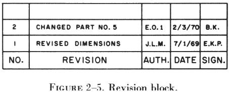
| When drawings contain such corrections, attention is directed
to the changes by lettering or numbering them and listing those changes
against the symbol in a revision block (figure 2-5). The revision block
contains the identification symbol, the date, the nature of the revision,
the authority for the change, and the name of the draftsman who made the
change.
To distinguish the corrected drawing from its previous version, many firms are including, as part of the title block, a space for entering the appropriate symbol to designate that the drawing has been changed or revised. |
|
Notes
Notes are added to drawings for various reasons. Some of these notes refer to methods of attachment or construction. Others give alternatives, so that the drawing can be used for different styles of the same object. Still others list modifications that are available. Notes may be found alongside the item to which they refer. If the notes are lengthy, they may be placed elsewhere on the drawing and identified by letters or numbers. Notes are used only when the information cannot be conveyed in the conventional manner or when it is desirable to avoid crowding the drawing. Figure 2-1 illustrates one method of depicting notes.
When the note refers to a specific part, a light line with an arrowhead leads from the note to the part. If it applies to more than one part, the note is so worded that no mistake can be made as to the parts to which it pertains. When there are several notes, they are generally grouped together and numbered consecutively.
Zone Numbers
Zone numbers on drawings are similar to the numbers and letters printed on the borders of a map. They are there to help locate a particular point. To find a point, mentally draw horizontal and vertical lines from the letters and numerals specified; the point where these lines would intersect is the area sought.
Use the same method to locate parts, sections, and views on large drawings, particularly assembly drawings. Parts numbered in the title block can be located on the drawing by finding the numbers in squares along the lower border. Zone numbers read from right to left.
Station Numbers
A numbering system is used on large assemblies for aircraft to locate stations such as fuselage frames. Fuselage Frame-Sta 185 indicates that the frame is 185 inches from the datum of the aircraft. The measurement is usually taken from the nose or zero station, but in some instances it may be taken from the fire wall or some other point chosen by the manufacturer.
The same station numbering system is used for wing and stabilizer frames. The measurement is taken from the center line or zero station of the aircraft.
Finish Marks
Finish marks are used to indicate the surface that must be machine finished. Such finished surfaces have a better appearance and allow a closer fit with adjoining parts. During the finishing process the required limits and tolerances must be observed. Do not confuse machined finishes with those of paint, enamel, chromium plating, and similar coating.
Tolerances
When a given dimension on a print shows an allowable variation, the plus (+) figure indicates the maximum, and the minus (-) figure the minimum, allowable variation. The sum of the plus and minus allowance figures is called tolerance. For example, using 0.225 + 0.0025 - 0.0005, the plus and minus figures indicate the part will be acceptable if it is not more than 0.0025 larger than the 0.225 given dimension, or not more than 0.0005 smaller than the 0.225 dimension. Tolerance in this example is 0.0030 (0.0025 max plus 0.005 min).
If the plus and minus allowances are the same, you will find them presented as 0.224 ± 0.0025. The tolerance would then be 0.0050. Allowance can be indicated in either fractional or decimal form. When very accurate dimensions are necessary, decimal allowances are used. Fractional allowances are sufficient when close dimensions are not required. Standard tolerances of -0.010 or -1/32 may be given in the title block of many drawings, to apply throughout the drawing.