PARALLELDCCIRCUITS
PARALLEL DC CIRCUITS
A circuit in which two or more electrical resistances, or loads, are
connected across the same voltage source is a parallel circuit. The parallel
circuit differs from the series circuit in that more than one path is provided
for current flow - the more paths added in parallel, the less opposition
to flow of electrons from the source. In a series circuit the addition
of resistance increases the opposition to current flow. The minimum requirements
for a parallel circuit are the following:
(1) a power source.
(2) conductors.
(3) a resistance or load for each current path.
(4) two or more paths for current flow.
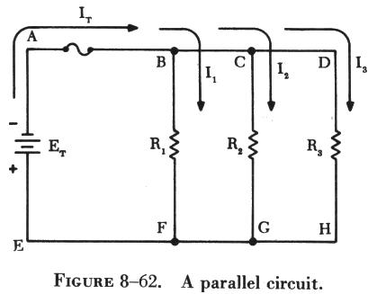
Figure 8-62 shows a parallel circuit with three paths for current flow.
Points A, B, C, and D are connected to the same conductor and are at the
same electrical potential. In a similar manner, points E, F, G, and H are
at the same potential. Since the applied voltage appears between points
A and E, the same voltage is applied between points B and F, points C and
G, and between points D and H. Thus, when resistors are connected in parallel
across a voltage source, each resistor has the same applied voltage, although
the currents through the resistors may differ depending on the values of
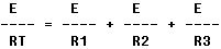
resistance. The voltage in a parallel circuit may be expressed as follows: 
Where ET is the applied voltage, E1 is the voltage across R1, E2 is
the voltage across R2, and E3 is the voltage across R3 (figure 8-62). |
|
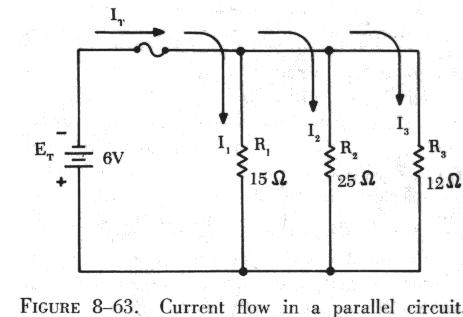 |
The current in a parallel circuit divides among the various branches
in a manner depending on the resistance of each branch (see figure 8-63).
A branch containing a small value of resistance will have a greater current
flow than a branch containing a high resistance. Kirchhoff's current law
states that the current flowing toward a point is equal to the current
flowing away from that point. Thus, the current flow in a circuit may be
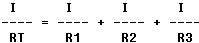
expressed mathematically as follows:
 where IT is the total
current and I1, I2, and I3 are the currents through R1, R2, and R3, respectively.
Kirchhoff's and Ohm's law can be applied to find the total current flow
in the circuit shown in figure 8-63. where IT is the total
current and I1, I2, and I3 are the currents through R1, R2, and R3, respectively.
Kirchhoff's and Ohm's law can be applied to find the total current flow
in the circuit shown in figure 8-63. |
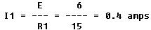
The current flow through the branch containing resistance R1 is
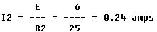
The current through R2 is
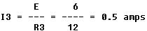
The current through R3 is
The total current, IT, is
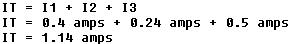
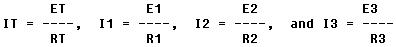
In a parallel circuit, IT = I1 + I2 + I3. By Ohm's law the following
relationships can be obtained:
Substituting these values in the equation for total current,
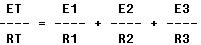
In a parallel circuit ET = E1 = E2 = E3. Therefore,
Dividing through by E gives,
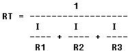
This equation is the reciprocal formula for finding the total or equivalent
resistance of a parallel circuit. Another form of the equation may be derived
by solving for RT.
An analysis of the equation for total resistance in a parallel circuit
shows that RT is always less than the smallest resistance in a parallel
circuit. Thus a 10 ohm, a 20 ohm, and a 40 ohm resistor connected in parallel
have a total resistance of less than 10 ohms.
If there are only two resistors in a parallel circuit, the reciprocal
formula is
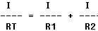
Simplified, this becomes:
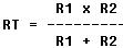
This simplified, shorter formula can be used when two resistances are
in parallel. Another method can be used for any number of resistors in
parallel if they are of equal resistance. The resistance value of one resistor
is divided by the number of resistors in parallel to determine the total
resistance. Expressed mathematically this becomes:

Where RT is the total resistance, R is the resistance of one resistor,
and N is the number of resistors.