RECTIFIERS
RECTIFIERS
Many devices in an aircraft require high amperage, low voltage dc for
operation. This power may be furnished by dc engine driven generators,
motor generator sets, vacuum tube rectifiers, or dry disk or solid state
rectifiers.
In aircraft with ac systems, a special dc generator is not desirable
since it would be necessary for the engine accessory section to drive an
additional piece of equipment. Motor generator sets, consisting of air
cooled ac motors that drive dc generators, eliminate this objection because
they operate directly off the ac power system. Vacuum tube or various types
of solid state rectifiers provide a simple and efficient method of obtaining
high voltage dc at low amperage. Dry disk and solid state rectifiers on
the other hand are an excellent source of high amperage at low voltage.
A rectifier is a device which transforms alternating current into direct
current by limiting or regulating the direction of current flow. The principal
types of rectifiers are dry disk, solid state, and vacuum tube rectifiers.
Solid state, or semiconductor, rectifiers are rapidly replacing all other
types; and, since dry disk and vacuum tube rectifiers and motor generators
are largely limited to older model aircraft, the major part of the study
of rectifiers will be devoted to solid state devices used for rectification.
Motor Generator
A motor generator is an ac motor and a dc generator combined in one
unit. This combination is often called a converter. Converters operate
directly on either single phase or three phase voltage. Converters used
on large aircraft are often operated by a three phase, 208 volt, ac system
and develop a direct current of 200 amperes at 30 volts with an approximate
28 ampere current drain on the ac system. Units similar to those used in
airplanes with dc systems are provided for voltage regulation and paralleling
of motor generator sets.
A motor generator offers a number of advantages as a source of dc power
in an airplane. With a motor generator, a momentary interruption of ac
power does not cut off the dc power completely, since the inertia of the
armature keeps it turning during the ac power interruption. Extreme temperature
changes affect a motor generator only slightly. Failure from overheating
is negligible compared to that in a vacuum tube rectifier when it is operated
above a safe temperature. In addition, a motor generator can be operated
at temperatures below those required by either dry disk or vacuum tube
rectifiers.
The greatest objection to a motor generator is that, like all rotary
devices, it requires considerable maintenance and creates a noise which
is especially objectionable if the set is in the cabin of the airplane.
For these reasons and, because of weight, space, and cost consideration,
the motor generator set is rapidly being replaced by various solid state
power sources.
Dry Disk
| Dry disk rectifiers operate on the principle that electric
current flows through a junction of two dissimilar conducting materials
more readily in one direction than it does in the opposite direction. This
is true because the resistance to current flow in one direction is low,
while in the other direction it is high. Depending on the materials used,
several amperes may flow in the direction of low resistance but only a
few milliamperes in the direction of high resistance.
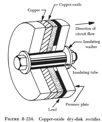
Three types of dry disk rectifiers may be found in aircraft: the copper
oxide rectifier, the selenium rectifier, and the magnesium copper-sulfide
rectifier. The copper oxide rectifier (figure 8-234) consists of a copper
disk upon which a layer of copper oxide has been formed by heating. It
may also consist of a chemical copper oxide preparation spread evenly over
the copper surface. Metal plates, usually lead plates, are pressed against
the two opposite faces of the disk to form a good contact. Current flow
is from the copper to the copper oxide.
The selenium rectifier consists of an iron disk, similar to a washer,
with one side coated with selenium. Its operation is similar to that of
the copper oxide rectifier. Current flows from the selenium to the iron.
The magnesium copper sulfide rectifier is made of washer shaped magnesium
disks coated with a layer of copper sulfide. The disks are arranged similarly
to the other types. Current flows from the magnesium to the copper sulfide. |
|
Solid State Rectifiers
In the study of transistors it was pointed out that the solid state
diode is manufactured from semiconductor material. It consists of N-type
and P-type material joined in a single crystal. The point, or junction,
where the two materials are in contact is called a P-N junction. This type
of semiconductor, regardless of rating or size, is called a junction diode.
The first type of semiconductor used was called the point contact diode.
It utilized a single type of semiconductor material, against which a tungsten
or phosphor-bronze wire, called a "cat whisker," was pressed or fused.
The point contact diode has been largely replaced by the junction diode
because of its limited current carrying capabilities. The most common semiconductor
materials are germanium and silicon. A typical junction diode is shown
in figure 8-235.
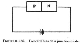
| In figure 8-236, the positive terminal of the battery is
connected to the P-type semiconductor material, and the negative terminal
is connected to the N-type. This arrangement constitutes forward bias.
The holes in the P-type material are repelled from the positive terminal
and move toward the junction. The electrons in the N-type material are
repelled from the negative terminal and likewise move toward the junction.
This decreases the space charge existing at the junction, and electron
current flow is maintained through the external circuit. The current in
the P-type material is in the form of holes, and in the N-type material
it is in the form of electrons. If the forward bias is increased, current
flow will increase. If the forward bias is increased excessively, it will
cause excessive current. The excessive current will increase thermal agitation
and the crystal structure will break down. One important fact worth remembering
is that all solid state devices are sensitive to heat and will be destroyed
if the heat becomes too intense. |
|
If the battery connections shown in figure 8-236 are reversed, the junction
diode is reverse biased. Now the holes are attracted toward the negative
terminal and away from the junction. The electrons are attracted toward
the positive terminal, also away from the junction. This widens the depletion
region, increases the space charge, and reduces current to a minimum condition.
It is possible to apply too high a reverse bias. When this happens, the
crystal structure will break down.
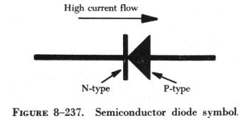 |
The symbol for the semiconductor diode is shown in figure 8-237. Note
that this is the same symbol used for other types of diodes, such as the
copper oxide and selenium dry disk rectifiers. The forward bias, or high
current, direction is always against the arrow of the symbol.
Figure 8-238 shows a typical characteristic
curve for a junction diode. As forward bias is increased a small amount,
current flow is increased a considerable amount. For this reason, solid
state devices are said to be current operated devices, since it is easier
to measure the relatively large changes in current flow as compared to
the small changes in applied voltage. With forward bias applied, the diode
displays a low resistance characteristic. On the other hand, with reverse
bias applied, a high resistance state exists. The most important characteristic
of a diode is that it allows current to flow in one direction only. This
permits solid state devices to be used in rectifier circuits. |
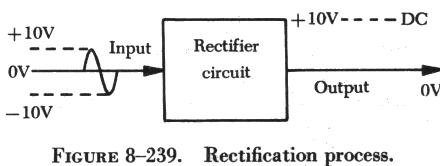
Rectification
Rectification is the process of changing alternating current to direct
current. When a semiconductor rectifier, such as a junction diode, is connected
to an ac voltage source, it is alternately biased forward and reverse,
in step with the ac voltage, as shown in figure 8-239.
In figure 8-240 a diode is placed in series with a source of ac power
and a load resistor. This is called a halfwave rectifier circuit.
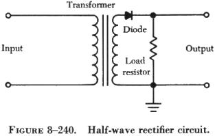
The transformer provides the ac input to the circuit; the diode provides
the rectification of the ac; and the load resistor serves two purposes:
(1) It limits the amount of current flow in the circuit to a safe level,
and (2) it develops an output signal due to the current flow through it.
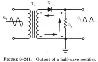
| Assume, in figure 8-241, that the top of the transformer
secondary is positive and the bottom negative. With this polarity, the
diode is forward biased, resistance of the diode is very low, and current
flows through the circuit in the direction of the arrows. The output (voltage
drop) across the load resistor follows the waveshape of the positive half
of the ac input. When the ac input goes in a negative direction, the top
of the transformer secondary becomes negative and the diode becomes reverse
biased.
With reverse bias applied to the diode, the resistance of the diode
becomes very great, and current flow through the diode and load resistor
becomes zero. (Remember that a very small current will flow through the
diode.) |
|
The output, taken across the load resistor, will be zero. If the position
of the diode were reversed, the output would be negative pulses.
In a halfwave rectifier, a half cycle of power is produced across the
load resistor for each full cycle of input power. To increase the output
power, a fullwave rectifier can be used. Figure 8-242
shows a fullwave rectifier, which is, in effect, two halfwave rectifiers
combined into one circuit. In this circuit a load resistor is used to limit
current flow and develop an output voltage, two diodes to provide rectification,
and a transformer to provide an ac input to the circuit. The transformer,
used in fullwave rectifier circuits, must be center tapped to complete
the path for current flow through the load resistor.
Assuming the polarities shown on the transformer, diode D1 will be forward
biased and current will flow from ground through the load resistor, through
diode D1, to the top of the transformer.
When the ac input changes direction, the transformer secondary will
assume an opposite polarity. Diode D2 is now forward biased and current
will flow in the opposite direction, from ground through the load resistor,
through diode D2, to the bottom half of the transformer.
When one diode is forward biased, the other is reverse biased. No matter
which diode is forward biased, current will flow through the load resistor
in the same direction; so the output will be a series of pulses of the
same polarity. By reversing both diodes, the output polarity will be reversed.
The voltage which is felt across a rectifier when reverse bias is being
applied is often referred to as "the inverse peak voltage." By definition,
this is the peak value of the instantaneous voltage across the rectifier
during the half cycle in which current does not flow or that reverse bias
is applied. If an inverse voltage is applied that is too large, the rectifier
will be destroyed. The term "breakdown voltage" is often used instead of
the term "inverse peak voltage rating," but both terms have the same meaning.
Breakdown voltage is the maximum voltage that the rectifier can stand while
it is not conducting (reverse biased); the inverse peak voltage is the
voltage actually being applied to the rectifier. As long as the inverse
peak voltage is lower than breakdown voltage, there will be no problem
of rectifier destruction.
Diode Bridge Rectifier Circuit
An advantageous modification of the fullwave diode rectifier is the
bridge rectifier. The bridge rectifier differs from the fullwave rectifier
in that a bridge rectifier does not require a center tapped transformer,
but does require two additional diodes.
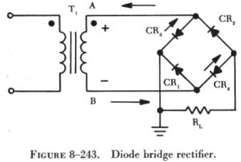
| To illustrate how a bridge rectifier performs, consider
a sine wave input which is on its positive alternation as denoted on the
schematic of figure 8-243. With the secondary of T1 functioning as the
bridge rectifier's power supply, point A is the most positive point of
the bridge, while B is the most negative. Current flow will be from B to
A through the forward biased diodes. As an aid in finding the path of electron
flow, consider the redrawn bridge circuit in figure 8-244. The forward
biased diodes, CR3 and CR4 are easily recognized. Voltage is dropped across
each voltage loop as indicated. Thus, on the positive half cycle input
CR3 and CR4 are both forward biased and CR1 and CR2 are reverse biased. |
|
As long as diode breakdown voltage is not exceeded, current flow will
be from point B up and across CR4 down and to the left across RL. After
current crosses RL, it will flow to point A through CR3. Notice that current
flow across RL is from right to left, or in respect to polarity, a negative
half cycle output for positive half cycle input.
Remember that, when tracing current flow for the negative half cycle,
electron flow through a diode is against the symbolic arrow and from negative
to a less negative or positive point. Therefore, no confusion should arise
when tracing electron flow up to and away from the common point between
CR3 and CR1. Although it may appear that CR1 as well as CR4 is forward
biased, such is not the case. The collector of CR1 is more negative than
its emitter; therefore, it is reverse biased.
Since, on the negative half cycle, CR1 and CR2 are forward biased, the
output signal on the negative half cycle is negative.
Since both half cycles of the input signal result in negative output
pulses, the bridge rectifier has accomplished the same goal as the fullwave
diode rectifier.