RESISTANCE
RESISTANCE
The property of a conductor of electricity that limits or restricts
the flow of electric current is called its resistance. Electrical pressure
is required to overcome this resistance, which is the attractive force
holding the electrons in their orbits. The materials from which electrical
conductors are manufactured, usually in the form of extruded wire, are
materials that offer very little resistance to current flow.
While wire of any size or resistance value may be used, the word "conductor"
usually refers to materials which offer low resistance to current flow,
and the word "insulator" describes materials that offer high resistance
to current. There is no distinct dividing line between conductors and insulators;
under the proper conditions, all types of material conduct some current.
Materials offering a resistance to current flow midway between the best
conductors and the poorest conductors (insulators) are sometimes referred
to as "semiconductors," and find their greatest application in the field
of transistors.
The best conductors are materials, chiefly metals, which possess a large
number of free electrons; conversely, insulators are materials having few
free electrons. The best conductors are silver, copper, gold, and aluminum,
but some nonmetals, such as carbon and water, can be used as conductors.
Materials such as rubber, glass, ceramics, and plastics are such poor conductors
that they are usually used as insulators. The current flow in some of these
materials is so low that it is usually considered zero. The unit used to
measure resistance is called the ohm. The symbol for the ohm is the Greek
letter omega (W). In mathematical formulas, the capital letter "R" refers
to resistance. The resistance of a conductor and the voltage applied to
it determine the number of amperes of current flowing through the conductor.
Thus, 1 ohm of resistance will limit the current flow to 1 ampere in a
conductor to which a voltage of 1 volt is applied.
Factors Affecting Resistance
Among the four major factors affecting the resistance of a conductor,
one of the most important is the type of conductor material. It has been
pointed out that certain metals are commonly used as conductors because
of the large number of free electrons in their outer orbits. Copper is
usually considered the best available conductor material, since a copper
wire of a particular diameter offers a lower resistance to current flow
than an aluminum wire of the same diameter. However, aluminum is much lighter
than copper, and for this reason as well as cost considerations, aluminum
is often used when the weight factor is important.
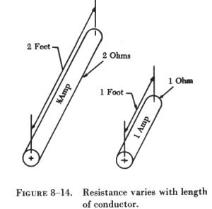
| A second resistance factor is the length of the conductor.
The longer the length of a given size of wire, the greater the resistance.
Figure 8-14 pictures two wire conductors of different lengths. If 1 volt
of electrical pressure is applied across the two ends of the conductor
that is 1 foot in length and the resistance to the movement of free electrons
is assumed to be 1 ohm, the current flow is limited to 1 ampere. If the
same size conductor is doubled in length, the same electrons set in motion
by the 1 volt applied now find twice the resistance; consequently, the
current flow will be reduced by one-half.
A third factor affecting the resistance of a conductor is cross-sectional
area, or the end surface of a conductor. This area may be triangular or
even square, but is usually circular. If the cross-sectional area of a
conductor is doubled, the resistance to current flow will be reduced in
half. This is true because of the increased area in which an electron can
move without collision or capture by an atom. Thus, the resistance varies
inversely with the cross-sectional area of a conductor. |
|
To compare the resistance of one conductor with that of another having
greater cross-section area, a standard, or unit, size of conductor be established.
The most convenient unit of measurement of wire diameter is the mil (0.001
of an inch). The most convenient unit of wire length is the foot. Using
these standards, the unit of size will be the mil-foot. Thus, a wire will
have unit size if it has a diameter of 1 mil and the length of 1 foot.
The resistance specified in ohms of a unit conductor of a certain material
is called the specific resistance, or specific resistivity, of the substance.
The square mil is a convenient unit of cross-sectional area for square
or rectangular conductors. A square mil is the area of a square, each side
of which measures 1 mil.
To compute the cross-sectional area of a conductor in square mils, the
length in mils of one side is squared. In the case of a rectangular conductor,
the length of one side is multiplied by the length of the other. For example,
a common rectangular bus bar (large, special conductor) is 3/8 inch thick
and 4 inches wide. The 3/8 inch thickness may be expressed as 0.375 inch.
Since 1,000 mils equals 1 inch, the width in inches can be converted to
4,000 mils. The cross-sectional area of the rectangular conductor is 0.375
x 4,000 or 1,500 square mils.
More common than the square or rectangular shape is the circular conductor.
Because the diameters of round conductors may be only a fraction of an
inch, it is convenient to express these diameters in mils to avoid the
use of decimals. The circular mil is the standard unit of wire cross-sectional
area used in American and English wire tables. Thus, the diameter of a
wire that is 0.025 inch may be more conveniently expressed as 25 mils.
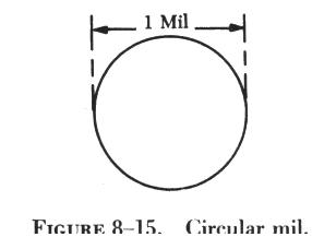 |
Figure 8-15 illustrates a circle having a diameter of 1 mil. The area
in circular mils is obtained by squaring the diameter measured in mils.
Thus, a wire with a diameter of 25 mils has an area of 25 squared, or 25
x 25, or 625 circular mils.
In comparing square and round conductors, it should be noted that the
circular mil is a smaller unit of area than the square mil. To determine
the circular mil area when the square mil area is known, the area in square
mil is divided by 0.7854. Conversely, to find the square mil area when
the circular mil area is known, the area in circular mils is multiplied
by 0.7854.
Wires are manufactured in sizes numbered according to a table known
as the American wire gauge (AWG). Wire diameters become smaller as the
gauge numbers become larger. This table is available to aviation technicians
for reference, not only on wire size but also resistance and cross-sectional
area. |
The last major factor influencing the resistance of a conductor is temperature.
Although some substances, such as carbon, show a decrease in resistance
as the ambient (surrounding) temperature increases, most materials used
as conductors increase in resistance as temperature increases. The resistance
of a few alloys, such as constantan and manganin, change very little as
the temperature changes. The amount of increase in the resistance of a
1 ohm sample of a conductor per degree rise in temperature above 0°
Centigrade (C), the assumed standard, is called the temperature coefficient
of resistance. For each metal this is a different value; for example, for
copper the value is approximately 0.00427 ohm. Thus, a copper wire having
a resistance of 50 ohms at a temperature of 0° C will have an increase
in resistance of 50 x 0.00427, or 0.214 ohm, for each degree rise in temperature
above 0° C. The temperature coefficient of resistance must be considered
where there is an appreciable change in temperature of a conductor during
operation. Charts listing the temperature coefficient of resistance for
different materials are available.