RHEOSTATS RHEOSTATS AND POTENTIOMETERS
 
The voltage dividers discussed thus far have consisted of resistors of various sizes across which a variety of voltage drops were developed. Rheostats and potentiometers are variable resistors which are sometimes used in connection with voltage dividers.

A rheostat is a variable resistor used to vary the amount of current flowing in a circuit. The rheostat is represented schematically as a two terminal resistance with a sliding arm contact. Figure 8-77 shows a rheostat connected in series with an ordinary resistance in a series circuit. As the slider arm moves from point A to B, the amount of rheostat resistance (AB) is increased. Since the rheostat resistance and the fixed resistance are in series, the total resistance in the circuit also increases, and the current in the circuit decreases. On the other hand, if the slider arm is moved toward point A, the total resistance decreases and the current in the circuit increases.

The potentiometer is a variable resistor which has three terminals. Two ends and a slider arm are connected in a circuit. A potentiometer is used to vary the amount of voltage in a circuit and is one of the most common controls used in electrical and electronic equipment. Some examples are the volume control in radio receivers and the brightness control in television receivers.

In A of figure 8-78 a potentiometer is used to obtain a variable voltage from a fixed voltage source to apply to an electrical load. The voltage applied to the load is the voltage between points B and C. When the slider arm is moved to point A, the entire voltage is applied to the electrical device (load); when the arm is moved to point C, the voltage applied to the load is zero. The potentiometer makes possible the application of any voltage between zero and full voltage to the load.

The current flowing through the circuit of figure 8-78 leaves the negative terminal of the battery and divides, one part flowing through the lower portion of the potentiometer (points C to B) and the other part through the load. Both parts combine at point B and flow through the upper portion of the potentiometer (points B to A) back to the positive terminal of the battery. In B of figure 8-78, a potentiometer and its schematic symbol are shown.

In choosing a potentiometer resistance, consideration should be given to the amount of current drawn by the load as well as the current flow through the potentiometer at all settings of the slider arm. The energy of the current through the potentiometer is dissipated in the form of heat.

It is important to keep this wasted current as small as possible by making the resistance of the potentiometer as large as practicable. In most cases, the resistance of the potentiometer can be several times the resistance of the load.

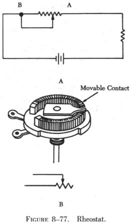
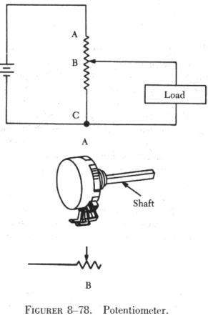
Rheostats and potentiometers are constructed of a circular resistance material over which a sliding contact moves. The resistance may be distributed in many ways, and the method used determines the classification as either linear or tapered. The linear type provides a resistance evenly distributed over its entire length, while the tapered has more resistance per unit length at one end than at the other. As an example, a one-half turn of a linear rheostat places one half of the total resistance between either end and the slider, while a one-half turn of a tapered rheostat places one-tenth (or any desired fraction) of the total resistance between one end and the slider.

Prefixes

In any system of measurements, a single set of units is usually not sufficient for all the computations involved in electrical repair and maintenance. Small distances, for example, can usually be measured in inches, but larger distances are more meaningfully expressed in feet, yards, or miles. Since electrical values often vary from numbers that are a millionth part of a basic unit of measurement to very large values, it is often necessary to use a wide range of numbers to represent the values of such units as 
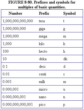
volts, amperes, or ohms. A series of prefixes which appear with the name of the unit have been devised for the various multiples or submultiples of the basic units. There are 12 of these prefixes, which are also known as conversion factors. Six of the most commonly used prefixes with a short definition of each are as follows:

FIGURE 8-79. Conversion Table.
1 ampere = 1,000,000 microamperes.
1 ampere = 1,000 milliamperes.
1 farad = 1,000,000,000,000 micromicrofarads.
1 farad = 1,000,000 microfarads.
1 farad = 1,000 millifarads
1 kilowatt = 1,000 watts.
1 megohm = 1,000,000 ohms.
1 microampere = .000001 ampere.
1 microfarad = .000001 farad.
1 microhm = .000001 ohm
1 microvolt = .000001 volt
1 microwatt = .000001 watt.
1 micromicrofarad = .000000000001 farad.
1 milliampere = .001 ampere.
1 millihenry = .001 henry.
1 millimho = .001 mho.
1 milliohm. = .001 ohm.
1 millivolt = .001 volt.
1 milliwatt = .001 watt.
1 volt = 1,000,000 microvolts.
1 volt = 1,000 millivolts.
1 watt = 1,000 milliwatts.
1 watt = .001 kilowatt.
Mega means one million (1,000,000).
Kilo means one thousand (1,000).
Centi means one-hundredth (1/100).
Milli means one-thousandth (1/1000).
Micro means one-millionth (1/1,000,000).
Micro micro means one-millionth-millionth (1/1,000,000,000,000).

One of the most extensively used conversion factors, kilo, can be used to explain the use of prefixes with basic units of measurement. Kilo means 1,000, and when used with volts is expressed as kilovolt, meaning 1,000 volts. The symbol for kilo is the letter "K". Thus, 1,000 volts is one kilovolt or 1KV. Conversely, one volt would equal one-thousandth of a KV, or 1/1000 KV. This could also be written 0.001 KV.

Similarly, the word "milli" means one-thousandth, and thus, 1 millivolt equals one-thousandth (1/1000) of a volt.

These prefixes may be used with all electrical units. They provide a convenient method for writing extremely large or small values. Most electrical formulas require the use of values expressed in basic units; therefore, all values must usually be converted before computation can be made. Figure 8-79 contains a conversion table which lists a number of the most commonly used electrical values.

Figure 8-80 contains a complete list of the multiples used to express electrical quantities, together with the prefixes and symbols used to represent each number.