An aircraft, even though made of the best materials and strongest parts, would be of doubtful value unless those parts were firmly held together. Several methods are used to hold metal parts together; they include riveting, bolting, brazing, and welding. The process used must produce a union that will be as strong as the parts that are joined.
Aluminum and its alloys are difficult to solder. To make a good union and a strong joint, aluminum parts can be welded, bolted, or riveted together. Riveting is satisfactory from the standpoint of strength and neatness, and is much easier to do than welding. It is the most common method used to fasten or join aluminum alloys in aircraft construction and repair.
A rivet is a metal pin used to hold two or more metal sheets, plates, or pieces of material together. A head is formed on one end when the rivet is manufactured. The shank of the rivet is placed through matched holes in two pieces of material, and the tip is then upset to form a second head to clamp the two pieces securely together. The second head, formed either by hand or by pneumatic equipment, is called a "shop head."
The shop head functions in the same manner as a nut on a bolt. In addition to their use for joining aircraft skin sections, rivets arc also used for joining spar sections, for holding rib sections in place, for securing fittings to various parts of the aircraft, and for fastening innumerable bracing members and other parts together.
Two of the major types of rivets used in the aircraft are the common solid shank type, which must be driven using a bucking bar, and the special (blind) rivets, which may be installed where it is impossible to use a bucking bar.
Solid Shank Rivets
Solid shank rivets are generally used in repair work. They are identified by the kind of material of which they are made, their head type, size of shank, and their temper condition. The designation of the solid shank rivet head type, such as universal head, roundhead, flathead, countersunk head, and brazier head, depends on the cross sectional shape of the head (see figure 6-33). The temper designation and strength are indicated by special markings on the head of the rivet.
The material used for the majority of aircraft solid shank rivets is aluminum alloy. The strength and temper conditions of aluminum alloy rivets are identified by digits and letters similar to those adopted for the identification of strength and temper conditions of aluminum and aluminum alloy stock. The 1100, 2017-T, 2024-T, 2117-T, and 5056 rivets are the five grades usually available.
The 1100 rivet, which is composed of 99.45 percent pure aluminum, is very soft. It is for riveting the softer aluminum alloys, such as 1100, 3003, and 5052, which are used for nonstructural parts (all parts where strength is not a factor). The riveting of map cases is a good example of where a rivet of 1100 aluminum alloy may be used.
The 2117-T rivet, known as the field rivet, is used more than any other for riveting aluminum alloy structures. The field rivet is in wide demand because it is ready for use as received and needs no further heat treating or annealing. It also has a high resistance to corrosion.
The 2017-T and 2024-T rivets are used in aluminum alloy structures where more strength is needed than is obtainable with the same size 2217-T rivet. These rivets are annealed and must be kept refrigerated until they are to be driven. The 2017-T rivet should be driven within approximately 1 hour and the 2024-T rivet within 10 to 20 minutes after removal from refrigeration.
The 5056 rivet is used for riveting magnesium alloy structures because of its corrosion resistant qualities in combination with magnesium.
Mild steel rivets are used for riveting steel parts. The corrosion resistant steel rivets are for riveting corrosion resistant steels in firewalls, exhaust stack brackets, and similar structures.
Monel rivets are used for riveting nickel-steel alloys. They can be substituted for those made of corrosion resistant steel in some cases.
The use of copper rivets in aircraft repair is limited. Copper rivets can be used only on copper alloys or nonmetallic materials such as leather.
Metal temper is an important factor in the riveting process, especially with aluminum alloy rivets. Aluminum alloy rivets have the same heat treating characteristics as aluminum alloy stock. They can be hardened and annealed in the same manner as aluminum. The rivet must be soft, or comparatively soft, before a good head can be formed. The 2017-T and 2024-T rivets are annealed before being driven. They harden with age.
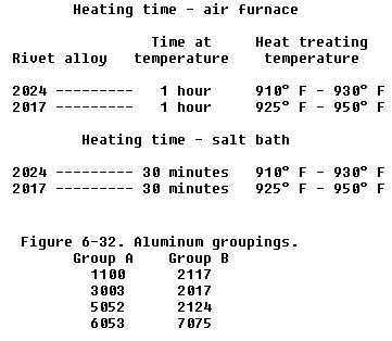
The process of heat treating (annealing) rivets is much the same as that for stock. Either an electric air furnace, a salt bath, or a hot oil bath is needed. The heat treating range, depending on the alloy, is 625° F to 950° F. For convenient handling, rivets are heated in a tray or a wire basket. They are quenched in cold water (70° F) immediately after heat treating.
The 2017-T and 2024-T rivets, which are heat treatable rivets, begin to age harden within a few minutes after being exposed to room temperature. Therefore, they must be used immediately after quenching or else be placed in cold storage.
The most commonly used means for holding heat treatable rivets at low temperature (below 32° F) is to keep them in an electric refrigerator. They are referred to as "icebox" rivets. Under this storage condition, they will remain soft enough for driving for periods up to 2 weeks. Any rivets not used within that time should be removed for reheat treating.
Icebox rivets attain about one-half their maximum strength in approximately 1 hour after driving and full strength in about 4 days. When 2017-T rivets are exposed to room temperature for 1 hour or longer, they must be subject to reheat treatment. This also applies to 2024-T rivets exposed to room temperature for a period exceeding 10 minutes.
Once an icebox rivet has been taken from the refrigerator, it should not be mixed with the rivets still in cold storage. If more rivets are removed from the icebox than can be used in 15 minutes, they should be placed in a separate container and stored for reheat treatment. Heat treatment of rivets may be repeated a number of times if done properly. Proper heating times and temperatures are:
Most metals, and therefore aircraft rivet stock, are subject to corrosion. Corrosion may be the result of local climatic conditions or the fabrication process used. It is reduced to a minimum by using metals which are highly resistant to corrosion and possess the correct strength to weight ratio.
Ferrous metals placed in contact with moist salt air will rust if not properly protected. Nonferrous metals, those without an iron base, do not rust, but a similar process known as corrosion takes place. The salt in moist air (found in the coastal areas) attacks the aluminum alloys. It is a common experience to inspect the rivets of an aircraft which has been operated near salt water and find them badly corroded.
If a copper rivet is inserted into an aluminum alloy structure, two dissimilar metals are brought in contact with each other. Remember, all metals possess a small electrical potential. Dissimilar metals in contact with each other in the presence of moisture cause an electrical current to flow between them and chemical byproducts to be formed. Principally, this results in the deterioration of one of the metals.
Certain aluminum alloys react to each other and, therefore, must be thought of as dissimilar metals. The commonly used aluminum alloys may be divided into the two groups shown in figure 6-32.

Avoid the use of dissimilar metals whenever possible. Their incompatibility is a factor which was considered when the AN Standards were adopted. To comply with AN Standards, the manufacturers must put a protective surface coating on the rivets. This may be zinc chromate, metal spray, or an anodized finish.
The protective coating on a rivet is identified by its color. A rivet coated with zinc chromate is yellow, an anodized surface is pearl gray, and the metal sprayed rivet is identified by a silvery gray color. If a situation arises in which a protective coating must be applied on the job, paint the rivet with zinc chromate before it is used and again after it is driven.
Identification
Markings on the heads of rivets are used to classify their characteristics. These markings may be either a raised teat, two raised teats, a dimple, a pair of raised dashes, a raised cross, a single triangle, or a raised dash;, some other heads have no markings.
The different markings indicate the composition of the rivet stock. As explained previously, the rivets have different colors to identify the protective surface coating used by the manufacturers.
Roundhead rivets are used in the interior of the aircraft, except where clearance is required for adjacent members. The roundhead rivet has a deep, rounded top surface. The head is large enough to strengthen the sheet around the hole and, at the same time, offer resistance to tension.
The flathead rivet, like the roundhead rivet, is used on interior structures. It is used where maximum strength is needed and where there isn't sufficient clearance to use a roundhead rivet. It is seldom, if ever, used on external surfaces. The brazier head rivet has a head of large diameter, which makes it particularly adaptable for riveting thin sheet stock (skin). The brazier head rivet offers only slight resistance to the airflow, and because of this factor, it is frequently used for riveting skin on exterior surfaces, especially on aft sections of the fuselage and empennage. It is used for riveting thin sheets exposed to the slipstream. A modified brazier head rivet is also manufactured; it is simply a brazier head of reduced diameter.
The universal head rivet is a combination of the roundhead, flathead, and brazier head. It is used in aircraft construction and repair in both interior and exterior locations. When replacement is necessary for protruding head rivets - roundhead, flathead, or brazier head - they can be replaced by universal head rivets.
The countersunk head rivet is flat topped and beveled toward the shank so that it fits into a countersunk or dimpled hole and is flush with the material's surface. The angle at which the head slopes may vary from 78° to 120°. The 100° rivet is the most commonly used type. These rivets are used to fasten sheets over which other sheets must fit. They are also used on exterior surfaces of the aircraft because they offer only slight resistance to the slipstream and help to minimize turbulent airflow.
The markings on the heads of rivets, indicate the material of which they are made and, therefore, their strength. Figure 6-33 identifies the rivet head markings and the materials indicated by them. Although there are three materials indicated by a plain head, it is possible to distinguish their difference by color. The 1100 is aluminum color; the mild steel is a typical steel color; and the copper rivet is a copper color. Any head marking can appear on any head style of the same material.
Each type of rivet is identified by a part number so that the user can select the correct rivet for the job. The type of rivet head is identified by AN or MS standard numbers. The numbers selected are in series and each series represents a particular type of head. (See Figure 6-33.) The most common numbers and the types of heads they represent are:
AN426 or MS20426 - countersunk head rivets (100°).
AN430 or MS20430 - roundhead rivets.
AN441 - flathead rivets.
AN456 - brazier head rivets.
AN470 or MS20470 - universal head rivets.
There are also letters and numbers added to a part number. The letters designate alloy content; the numbers, rivet diameter and length. The letters in common use for alloy designation are:
A - Aluminum alloy, 1100 or 3003 composition.
AD - Aluminum alloy, 2117-T composition.
D - Aluminum alloy, 2017-T composition.
DD - Aluminum alloy, 2024-T composition.
B - Aluminum alloy, 5056 composition.
C - Copper.
M - Monel.
The absence of a letter following the AN standard number indicates a rivet manufactured from mild steel.
The first number following the material composition letters expresses the diameter of the rivet shank in 32nds of an inch. Examples: 3, 3/32nds; 5, 5/32nds; etc. (See figure 6-34).
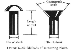
The last number(s), separated by a dash from the preceding number, expresses the length of the rivet shank in 16ths of an inch. Examples: 3, 3/16ths; 7, 7/16ths; 11, 11/16ths; etc. (See figure 6-34.)
An example of identification marking of a rivet is:
AN470AD3-5 - complete part number.
AN - Air Force-Navy standard number.
470 - universal head rivet.
AD - 2117-T aluminum alloy.
3 - 3/32nds in diameter.
5 - 5/16ths in length.
Special (Blind) Rivets
There are many places on an aircraft where access to both sides of a riveted structure or structural part is impossible, or where limited space will not permit the use of a bucking bar. Also, in the attachment of many nonstructural parts such as aircraft interior furnishings, flooring, deicing boots, and the like, the full strength of solid shank rivets is not necessary.
For use in such places, special rivets have been designed which can be bucked from the front. They are sometimes lighter than solid shank rivets, yet amply strong for their intended use. These rivets are produced by several manufacturers and have unique characteristics that require special installation tools, special installation procedures and special removal procedures. That is why they are called special rivets. Because these rivets are often inserted in locations where one head (usually the shop head) cannot be seen, they are also called blind rivets.
Mechanically Expanded Rivets
Two classes of mechanically expanded rivets will be discussed here:
(1) Nonstructural
(a) Selfplugging (friction lock) rivets
(b) Pull thru rivets
(2) Mechanical lock, flush fracturing, self plugging rivets.
Self-Plugging
The self-plugging (friction lock) blind rivets are manufactured by several companies: the same general basic information about their fabrication, composition, uses, selection, installation, inspection, and removal procedures apply to all of them.
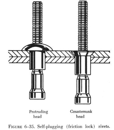
Self-plugging (friction lock) rivets are fabricated in two parts: A rivet head with a hollow shank or sleeve, and a stem that extends through the hollow shank. Figure 6-35 illustrates a protruding head and a countersunk head self-plugging rivet produced by one manufacturer.
Several events, in their proper sequence, occur when a pulling force is applied to the stem of the rivet: (1) The stem is pulled into the rivet shank; (2) the mandrel portion of the stem forces the rivet shank to expand; and (3) when friction (or pulling action pressure) becomes great enough it will cause the stem to snap at a breakoff groove on the stem. The plug portion (bottom end of the stem) is retained in the shank of the rivet giving the rivet much greater shear strength than could be obtained from a hollow rivet.
Self-plugging (friction lock) rivets are fabricated in two common head styles: (1) A protruding head similar to the MS20470 or universal head, and (2) a 100° countersunk head. Other head styles are available from some manufacturers.
The stem of the self-plugging (friction lock) rivet may have a knot or knob on the upper portion, or it may have a serrated portion as shown in figure 6-35.
Self-plugging (friction lock) rivets are fabricated from several materials. Rivets are available in the following material combinations: stem 2017 aluminum alloy and sleeve 2117 aluminum alloy; stem 2017 aluminum alloy and sleeve 5056 aluminum alloy; and stem steel and sleeve steel.
Self-plugging (friction lock) rivets are designed so that installation requires only one person; it is not necessary to have the work accessible from both sides. The pulling strength of the rivet stem is such that a uniform job can always be assured. Because it is not necessary to have access to the opposite side of the work, self-plugging (friction lock) rivets can be used to attach assemblies to hollow tubes, corrugated sheet, hollow boxes, etc. Because a hammering force is not necessary to install the rivet, it can be used to attach assemblies to plywood or plastics.
Factors to consider in the selection of the correct rivet for installation
are: (1) Installation location, (2) composition of the material being riveted,
(3) thickness of the material being riveted, and (4) strength desired.
| If the rivet is to be installed on an aerodynamically smooth surface,
or if clearance for an assembly is needed, countersunk head rivets should
be selected. In other areas where clearance or smoothness is not a factor,
the protruding head type rivet may be utilized.
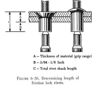
Material composition of the rivet shank will depend upon the type of material being riveted. Aluminum alloy 2117 shank rivets can be used on most aluminum alloys. Aluminum alloy 5056 shank rivets should be used when the material being riveted is magnesium. Steel rivets should always be selected for riveting assemblies fabricated from steel. The thickness of the material being riveted determines the overall length of the shank of the rivet. As a general rule, the shank of the rivet should extend beyond the material thickness approximately 3/64 inch to 1/8 inch before the stem is pulled (see figure 6-36). |
 |
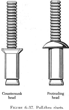 |
Pull-Thru Rivets
The pull-thru blind rivets are manufactured by several companies; the same general basic information about their fabrication, composition, uses, selection, installation, inspection, and removal procedures apply to all of them. Pull-thru rivets are fabricated in two parts: A rivet head with a hollow shank or sleeve and a stem that extends through the hollow shank. Figure 6-37 illustrates a protruding head and a countersunk head pull-thru rivet. Several events, in their proper sequence, occur when a pulling force is applied to the stem of the rivet: (1) The stem is pulled thru the rivet shank; (2) the mandrel portion of the stem forces the shank to expand forming the blind head and filling the hole. Pull-thru rivets are fabricated in two common head styles: (1) Protruding head similar to the MS20470 or universal head, and (2) a 100° countersunk head. Other head styles are available from some manufacturers. |
| Pull-thru rivets are fabricated from several materials.
Following are the most commonly used: 2117-T4 aluminum alloy, 5056 aluminum
alloy, monel.
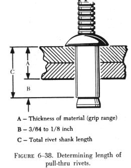
Pull-thru rivets are designed so that installation requires only one person; it is not necessary to have the work accessible from both sides. Factors to consider in the selection of the correct rivet for installation are: (1) Installation location, (2) composition of the material being riveted, (3) thickness of the material being riveted, and (4) strength desired. The thickness of the material being riveted determines the overall length of the shank of the rivet. As a general rule, the shank of the rivet should extend beyond the material thickness approximately 3/64 inch to 1/8 inch before the stem is pulled. See figure 6-38. |
 |
Each company that manufactures pull-thru rivets has a code number to
help users obtain correct rivet for the grip range of a particular installation.
In addition, MS numbers are used for identification purposes. Numbers are
similar to those shown on the preceding page.
 |
Self-Plugging Rivets
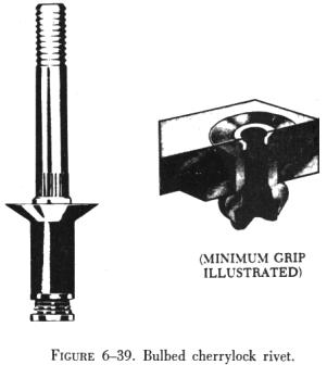
Self-plugging (mechanical lock) rivets are similar to self-plugging (friction lock) rivets, except for the manner in which the stem is retained in the rivet sleeve. This type of rivet has a positive mechanical locking collar to resist vibrations that cause the friction lock rivets to loosen and possibly fall out. (See figure 6-41.) Also, the mechanical locking type rivet stem breaks off flush with the head and usually does not require further stem trimming when properly installed. Self-plugging (mechanical lock) rivets display all the strength characteristics of solid shank rivets and in most cases can be substituted rivet for rivet. Bulbed Cherrylock Rivets The large blind head of this fastener introduced the word "bulb" to blind rivet terminology. In conjunction with the unique residual preload developed by the high stem break load, its proven fatigue strength makes it the only blind rivet interchangeable structurally with solid rivets (figure 6-39). |
Wiredraw Cherrylock Rivets
A wide range of sizes, materials and strength levels to select from.
This fastener is especially suited for sealing applications and joints
requiring an excessive amount of sheet takeup (figure
6-40).
Huck Mechanical Locked Rivets
Self-plugging (mechanical lock) rivets are fabricated in two sections - a head and shank (including a conical recess and locking collar in the head), and a serrated stem that extends through the shank. Unlike the friction lock rivet, the mechanical lock rivet has a locking collar that forms a positive lock for retention of the stem in the shank of the rivet. This collar is seated in position during the installation of the rivet.
Material
Self-plugging (mechanical lock) rivets are fabricated with sleeves (rivet shanks) of 2017 and 5056 aluminum alloys, monel, or stainless steel.
The mechanical lock type of self-plugging rivet can be used in the same applications as the friction lock type of rivet. In addition, because of its greater stem retention characteristic, installation in areas subject to considerable vibration is recommended.
The same general requirements must be met in the selection of the mechanical lock rivet as for the friction lock rivet. Composition of the material being joined together determines the composition of the rivet sleeve, for example, 2017 aluminum alloy rivets for most aluminum alloys and 5056 aluminum rivets for magnesium.
Figure 6-42 depicts the sequences of a typical mechanically locked blind rivet. The form and function may vary slightly between blind rivet styles and specifics should be obtained from manufacturers.
Head Styles
Self-plugging mechanical locked blind rivets are available in several head styles (figure 6-43) depending on the installation requirements.
Diameters
Shank diameters are measured in 1/32 inch increments and are generally
identified by the first dash number: 3/32 diameter = -3; 1/8 diameter =
-4; etc. Both nominal and 1/64 inch oversize diameters are available.
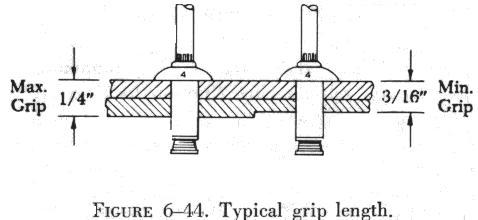
| Grip Length
Grip length refers to the maximum total sheet thickness to be riveted
and is measured in 1/6 of an inch. This is generally identified by the
second dash number. Unless otherwise noted, most blind rivets have their
grip lengths (maximum grip) marked on the rivet head and have a total grip
range of 1/16 inch. Figure 6-44 demonstrates a typical grip accommodation.
|
 |
To determine the proper grip rivet to use, measure the material thickness with a grip selection gauge (available from blind rivet manufacturers). The proper use of a grip selector gauge is shown in figure 6-45.
The thickness of the material being riveted determines the overall length of the shank of the rivet. As a general rule, the shank of the rivet should extend beyond the material thickness approximately 3/64 inch to 1/8 inch before the stem is pulled (see figure 6-46).
Rivet Identification
Each company that manufactures self-plugging (friction lock) rivets has a code number to help users obtain the correct rivet for the grip range or material thickness of a particular installation. In addition, MS numbers are used for identification purposes.
Rivnuts
This is the trade name of a hollow, blind rivet made of 6053 aluminum alloy, counterbored and threaded on the inside. Rivnuts can be installed by one person using a special tool which heads the rivet on the blind side of the material. The Rivnut is threaded on the mandrel of the heading tool and inserted in the rivet hole. The heading tool is held at right angles to the material, the handle is squeezed, and the mandrel crank is turned clockwise after each stroke. Continue squeezing the handle and turning the mandrel crank of the heading tool until a solid resistance is felt, which indicates that the rivet is set.
The Rivnut is used primarily as a nut plate and in the attachment of deicer boots to the leading edges of wings. It may be used as a rivet in secondary structures or for the attachment of accessories such as brackets, instruments, or soundproofing materials.
Rivnuts are manufactured in two head types, each with two ends; the flat head with open or closed end, and the countersunk head with open or closed end. All Rivnuts, except the thin head countersunk type, are available with or without small projections (keys) attached to the head to keep the Rivnut from turning. Keyed Rivnuts are used as a nut plate, while those without keys are used for straight blind riveting repairs where no torque loads are imposed. A keyway cutter is needed when installing Rivnuts which have keys.
The countersunk style Rivnut is made with two different head angles; the 100° with 0.048 and 0.063 inch head thickness, and the 115° with 0.063 inch head thickness. Each of these head styles is made in three sizes, 6-32, 8-32, and 10-32. These numbers represent the machine screw size of the threads on the inside of the Rivnut. The actual outside diameters of the shanks are 3/16 inch for the 6-32 size, 7/32 inch for the 8-32 size, and 1/4 inch for the 10-32 size.
Open end Rivnuts are the most widely used and are recommended in preference to the closed end type wherever possible. However, closed end Rivnuts must be used in pressurized compartments.
Rivnuts are manufactured in six grip ranges. The minimum grip length is indicated by a plain head, and the next higher grip length by one radial dash mark on the head. Each succeeding grip range is indicated by an additional radial dash mark until five marks indicate the maximum range.
Notice in figure 6-51 that some part number codes consist of a "6", an "8", or a "10", a "dash", and two or three more numbers. In some, the dash is replaced by the letters "K" or "KB". The first number indicates the machine screw size of the thread, and the last two or three numbers indicate the maximum grip length in thousandths of an inch. A dash between the figures indicates that the Rivnut has an open end and is keyless; a "B" in place of the dash means it has a closed end and is keyless; a "K" means it is an open end and has a key; and a "KB" indicates that it has a closed end and a key. If the last two or three numbers are divisible by five, the Rivnut has a flathead; if they are not divisible by five, the Rivnut has a countersunk head.
An example of a part number code is:
10 KB 106
10 = Grip length.
KB = Closed end and key.
106 = Screw and thread size.
Dill Lok-Skrus and Dill Lok-Rivets
Dill "Lok-Skru" and "Lok-Rivet" (see figure 6-52) are trade names for internally threaded rivets. They are used for blind attachment of such accessories as fairings, fillets, access door covers, door and window frames, floor panels, and the like. Lok-Skrus and Lok-Rivets are similar to the Rivnut in appearance and application; however, they come in two parts and require more clearance on the blind side than the Rivnut to accommodate the barrel.
The Lok-Rivet and the Lok-Skru are alike in construction, except the Lok-Skru is tapped internally for fastening an accessory by using an attaching screw, whereas the Lok-Rivet is not tapped and can be used only as a rivet. Since both Lok-Skrus and Lok-Rivets are installed in the same manner, the following discussions for the Lok-Skru also applies to the Lok-Rivet.
The main parts of a Lok-Skru are the barrel, the head, and an attachment
screw. The barrel is made of aluminum alloy and comes in either closed
or open ends. The head is either aluminum alloy or steel, and the attachment
screw is made of steel. All of the steel parts are cadmium plated, and
all of aluminum parts are anodized to resist corrosion. When installed,
the barrel screws up over the head and grips the metal on the blind side.
The attaching screw is then inserted if needed. There are two head types,
the flathead and the countersunk head. The Lok-Skru is tapped for 7-32,
8-32, 10-32, or 10-24 screws, and the diameters vary from 0.230 inch for
6-32 screws, to 0.292 inch for 10-32 screws. Grip ranges vary from 0.010
inch to 0.225 inch.
| Deutsch Rivets
This rivet is a high strength blind rivet used on late model aircraft. It has a minimum shear strength of 75,000 psi, and can be installed by one man. The Deutsch rivet consists of two parts, the stainless steel sleeve and the hardened steel drive pin (see figure 6-53). The pin and sleeve are coated with a lubricant and a corrosion inhibitor. The Deutsch rivet is available in diameters of 3/16, 1/4, or 3/8 inch. Grip lengths for this rivet range from 3/16 to 1 inch. Some variation is allowed in grip length when installing the rivet; for example, a rivet with a grip length of 3/16 inch can be used where the total thickness of materials is between 0.198 and 0.228 inch. |
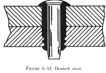 |
When driving a Deutsch rivet, an ordinary hammer or a pneumatic rivet
gun and a flathead set are used. The rivet is seated in the previously
drilled hole and then the pin is driven into the sleeve. The driving action
causes the pin to exert pressure against the sleeve and forces the sides
of the sleeve out. This stretching forms a shop head on the end of the
rivet and provides positive fastening. The ridge on the top of the rivet
head locks the pin into the rivet as the last few blows are struck.
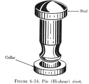
| Pin Rivets
Pin (Hi-shear) rivets are classified as special rivets but are not of the blind type. Access to both sides of the material is required to install this type of rivet. Pin rivets have the same shear strength as bolts of equal diameters, are about 40 percent of the weight of a bolt, and require only about one-fifth as much time for installation as a bolt, nut, and washer combination. They are approximately three times as strong as solid shank rivets. Pin rivets are essentially threadless bolts. The pin is headed at one end and is grooved about the circumference at the other. A metal collar is swaged onto the grooved end effecting a firm, tight fit (see figure 6-54). Pin rivets are fabricated in a variety of materials but should be used only in shear applications. They should never be used where the grip length is less than the shank diameter. |
 |
Part numbers for pin rivets can be interpreted to give the diameter and grip length of the individual rivets. A typical part number breakdown would be:
NAS 177 - 14 - 17
NAS = National Aircraft Standard.
177 = 100° countersunk head rivet. OR 178 = flathead rivet
14 = Nominal diameter in 32nds of an inch.
17 = Maximum grip length in 16ths of an inch.