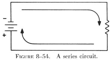
| The series circuit is the most basic of electrical circuits. All other types of circuits are elaborations or combinations of series circuits. Figure 8-54 is an example of a simple series circuit. It is a circuit because it provides a complete path for current to flow from the negative to the positive terminal of the battery. It is a series circuit because there is only one possible path in which current can flow, as indicated by the arrows showing the direction of electron movement. It is also called a series circuit because current must pass through the circuit components, the battery and the resistor, one after the other, or "in series." |
|
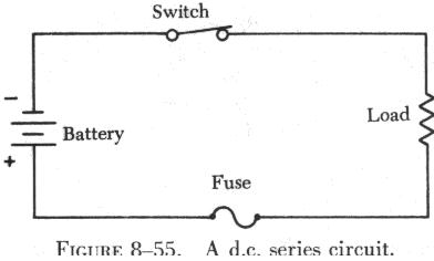 |
The circuit shown in figure 8-55 contains the basic components required
for any circuit: a source of power (battery), a load or current limiting
resistance (resistor), and a conductor (wire). Most practical circuits
contain at least two other items: a control device (switch) and a safety
device (fuse). With all five components in the circuit it would appear
as shown in figure 8-55, which is a dc series circuit.
In the dc or direct current circuit, current flows in one direction from the negative terminal of the battery through the switch (which must be closed) through the load resistance and the fuse to the positive terminal of the battery. |
To discuss the behavior of electric current in a dc series circuit,
figure 8-56 is redrawn in figure 8-57 to include three ammeters and two
resistors. Since an ammeter measures the intensity of current flow, three
have been located in the circuit to measure the current flowing at various
points in the circuit.
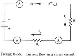 |
With the switch closed to complete the circuit, all three ammeters will indicate the same amount of current. This is an important characteristic of all series circuits: No matter how many components are included in a series circuit, the current is the same intensity throughout the circuit. While it is true that an increase in the number of circuit components will increase the resistance to current flow in the circuit, whatever the value of current flowing in the circuit, it will be the same value at all points in the circuit.
In figure 8-56, the current through resistor R1 is labeled I1 and the current through resistor R2 is labeled I2. If the total current in the circuit is IT, the formula describing the current flow is,
![]()
If the number of resistors is increased to five, the formula will be
![]()
Without indicating how much current is flowing, it will always be true that the current through any resistor in a series circuit will be the same as that through any other resistor.
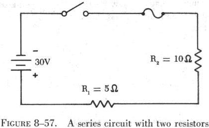
Figure 8-57 is a series circuit containing two resistances. In order to determine the amount of current flow in this circuit, it is necessary to know how much resistance or opposition the current flow will encounter. Thus, the second characteristic of series circuits is: Total resistance in a series circuit is the sum of the separate resistances in the circuit. Stated as a formula, this becomes
![]()
In figure 8-57, this is
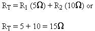
The total resistance of the circuit in figure 8-57 is 15 ohms. It is important to remember that, if the circuit were altered to include 10, 20, or even 100 resistors, the total resistance would still be the sum of all the separate resistances. It is also true that there is a certain negligible resistance in the battery, as well as in the fuse and the switch. These small values of resistance will not be considered in determining the value of current flow in this circuit.
The Ohm's law formula for finding current is I = E/R. Since the battery voltage is 30 volts and the total circuit resistance is 15 ohms, the equation becomes
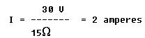
The current flow is 2 amperes (sometimes the word amperes is shortened to amps), and this value of current is everywhere in the circuit.
To consider what effect a change in resistance will have on current flow when the voltage remains constant, the total resistance is doubled to 30 ohms. Using Ohm's law
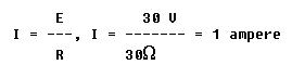
It can be seen that current will be reduced to half its former value when resistance is doubled. On the other hand, if voltage remains constant, and resistance is reduced to half its former value the current will double its original value.
Thus, if voltage remains constant and resistance increases, current must decrease. Conversely, if resistance decreases, current must increase.
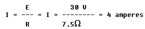
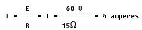
However, if resistance is held constant and voltage is doubled, the
current flow will double its original value. If the voltage applied to
the circuit in figure 8-58 is doubled to 60 volts and the original value
of resistance is maintained at 15 ohms,
and if voltage is reduced to half its original value, with resistance constant, current will decrease to half its original value.
Thus, if resistance remains constant, and voltage increases, current
must also increase. If voltage decreases, current decreases also.
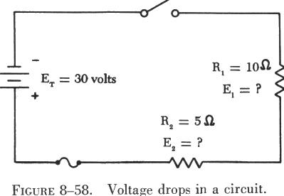
| It is important to distinguish between the terms "voltage"
and "voltage drop" in discussing series circuits. Voltage drop refers to
the loss in electrical pressure caused by forcing electrons through a resistance.
In figure 8-58, the applied voltage (the battery) is 30 volts and is labeled
ET.
Since there are two resistances in the circuit, there will be two separate voltage drops. These two voltage drops will be the loss in electrical pressure used to force electrons through the resistances. The amount of electrical pressure required to force a given number of electrons through a resistance is proportional to the size of the resistance. Thus, the voltage drop across R1 will be twice that across R2 since R1 has two times the resistance value of R2. The drop across R1 is labeled E1, and that across R2 is E2. The current, I, is the same throughout the circuit. |
 |
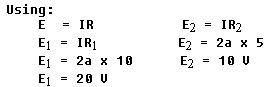
If the voltage drops (used) across the two resistors are added (10 V
+ 20 V), a value equal to the applied voltage, 30 volts, is obtained. This
confirms the basic formula for series circuits: ![]()
In any dc series circuit, a missing quantity such as voltage, resistance, or current can be calculated by using Ohm's law if any two of the quantities are known.
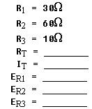
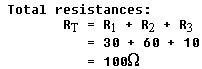
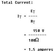
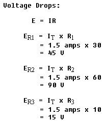
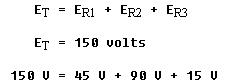
Figure 8-59 is a series circuit containing three known values of resistance
and an applied voltage of 150 volts. Using these values, the unknown circuit
quantities can be determined by applying Ohm's law as follows:
 |
 |
 |
 |
Kirchhoff Laws
In 1847, a German physicist, G. R. Kirchhoff, elaborated on Ohm's law and developed two statements that are known as Kirchhoff's laws for current and voltage. An understanding of these laws enables the aircraft technician to gain a better understanding of the behavior of electricity. Using Kirchhoff's laws, it is possible to find: (1) The current in each branch of a network circuit when both the resistance and the electromotive force in each branch are known, or (2) the electromotive force in each branch when both the resistance of, and the current in, each branch are known. These laws are stated as follows:
Current Law - The algebraic sum of the currents at any junction of conductors in a circuit is zero. This means that the amount of current flowing away from a point in a circuit is equal to the amount flowing to that point.
Voltage Law - The algebraic sum of the applied voltage and the voltage drop around any closed circuit is zero, which means that the voltage drop around any closed circuit is equal to the applied voltage.
When applying Kirchhoff's laws, use the following procedures to simplify the work:
1. When the direction of current is not apparent, assume a direction of flow. If the assumption is wrong, the answer will be numerically correct but preceded by a negative sign.
2. Place polarity markings (plus and minus signs) on all resistors and
batteries in the circuit being solved. The assumed direction of current
flow will not affect the polarities of the batteries, but it will affect
the polarity of the voltage drop on resistors. Therefore, the voltage drop
should be marked so that the end of a resistor into which the current is
assumed to flow is negative, and the end from which it leaves is positive.
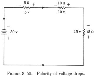
| In the statements of Kirchhoff's laws, the term algebraic sum was used. An algebraic sum differs from an arithmetic sum in that both the magnitude and the sign of each number must be considered. In electrical circuits a voltage drop occurs when current flows through a resistor. The magnitude of the voltage is determined by the size of the resistor and the amount of current flow. The polarity (sign) of the voltage drop is determined by the direction of the current flow. For example, observe the polarities of the applied electromotive force (e.m.f) and the voltage drop as shown in figure 8-60. The applied e.m.f. causes electrons to flow through the opposition offered by the resistances. The voltage drop across each resistance is therefore opposite in polarity to that of the applied e.m.f. Note that the side of each resistor where the current enters is labeled the negative side. |
 |
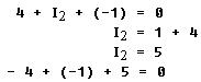
A portion of a circuit which illustrates Kirchhoff's current law is shown in figure 8-61. The current flowing through resistor R1 has an intensity of four amperes. The current flowing through resistor R3 has a magnitude of one ampere and is flowing into the same junction as the current through R1. Using Kirchhoff's current law, it is possible to determine how much current is flowing through R2 and whether it is flowing toward or away from the common junction. This is expressed in equation form as:
![]()
Substituting the current values in the equation gives
Kirchhoff's current law finds a wider application in more complex parallel or series-parallel circuits.
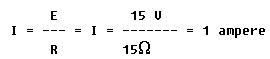
figure 8-61(B) is a series dc circuit which is used to demonstrate Kirchhoff's voltage law.
The total resistance is the sum of R1, R2, and R3 which is 30 ohms. Since the applied voltage is 30 volts, the current flowing in the circuit is 1 ampere. Therefore, the voltage drops across R1, R2, and R3 are 5 volts, 10 volts, and 15 volts, respectively. The sum of the voltage drops is equal to the applied voltage of 30 volts.
This circuit may also be solved by using the polarities of the voltages and showing that the algebraic sum of the voltages is zero. Consider voltages positive if the (+) sign is met first and negative if the (-) sign is met first when tracing the current flow. By starting at the battery and going in the direction of current flow (as indicated by the arrows) the following equation may be set up:
![]()
The point to start around the circuit and the polarity to use are arbitrary and are a matter of choice for each circuit.