TRANSFORMERS
TRANSFORMERS
| A transformer changes electrical energy of a given voltage
into electrical energy at a different voltage level. It consists of two
coils which are not electrically connected, but which are arranged in such
a way that the magnetic field surrounding one coil cuts through the other
coil. When an alternating voltage is applied to (across) one coil, the
varying magnetic field set up around that coil creates an alternating voltage
in the other coil by mutual induction. A transformer can also be used with
pulsating dc, but a pure dc voltage cannot be used, since only a varying
voltage creates the varying magnetic field which is the basis of the mutual
induction process.
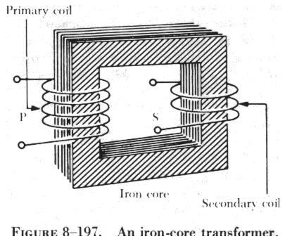
A transformer consists of three basic parts, as shown in figure 8-197.
These are an iron core which provides a circuit of low reluctance for magnetic
lines of force, a primary winding which receives the electrical energy
from the source of applied voltage, and a secondary winding which receives
electrical energy by induction from the primary coil. |
|
The primary and secondary of this closed core transformer are wound
on a closed core to obtain maximum inductive effect between the two coils.
There are two classes of transformers: (1) Voltage transformers used
for stepping up or stepping down voltages, and (2) current transformers
used in instrument circuits.
In voltage transformers the primary coils are connected in parallel
across the supply voltage, as shown in A of figure 8-198. The primary windings
of current transformers are connected in series in the primary circuit
(B of figure 8-198). Of the two types, the voltage
transformer is the more common.
There are many types of voltage transformers. Most of these are either
step up or step down transformers. The factor which determines whether
a transformer is a step up or step down type is the "turns" ratio. The
turns ratio is the ratio of the number of turns in the primary winding
to the number of turns in the secondary winding. For example, the turns
ratio of the step down transformer shown in A of figure
8-199 is 5 to 1, since there are five times as many turns in the primary
as in the secondary. The step up transformer shown in B of figure
8-199 has a 1 to 4 turns ratio.
The ratio of the transformer input voltage to the output voltage is
the same as the turns ratio if the transformer is 100 percent efficient.
Thus, when 10 volts are applied to the primary of the transformer shown
in A of figure 8-199, two volts are induced in
the secondary. If 10 volts are applied to the primary of the transformer
in B of figure 8-199, the output voltage across the terminals of the secondary
will be 40 volts.
No transformer can be constructed that is 100 percent efficient, although
iron core transformers can approach this figure. This is because all the
magnetic lines of force set up in the primary do not cut across the turns
of the secondary coil. A certain amount of the magnetic flux, called leakage
flux, leaks out of the magnetic circuit. The measure of how well the flux
of the primary is coupled into the secondary is called the "coefficient
of coupling." For example, if it is assumed that the primary of a transformer
develops 10,000 lines of force and only 9,000 cut across the secondary,
the coefficient of coupling would be 0.9 or, stated another way, the transformer
would be 90 percent efficient.
When an ac voltage is connected across the primary terminals of a transformer,
an alternating current will flow and selfinduce a voltage in the primary
coil which is opposite and nearly equal to the applied voltage. The difference
between these two voltages allows just enough current in the primary to
magnetize its core. This is called the exciting, or magnetizing, current.
The magnetic field caused by this exciting current cuts across the secondary
coil and induces a voltage by mutual induction. If a load is connected
across the secondary coil, the load current flowing through the secondary
coil will produce a magnetic field which will tend to neutralize the magnetic
field produced by the primary current. This will reduce the selfinduced
(opposition) voltage in the primary coil and allow more primary current
to flow. The primary current increases as the secondary load current increases,
and decreases as the secondary load current decreases. When the secondary
load is removed, the primary current is again reduced to the small exciting
current sufficient only to magnetize the iron core of the transformer.
If a transformer steps up the voltage, it will step down the current
by the same ratio. This should be evident if the power formula is considered,
for the power (I x E) of the output (secondary) electrical energy is the
same as the input (primary) power minus that energy loss in the transforming
process. Thus, if 10 volts and 4 amps (40 watts of power) are used in the
primary to produce a magnetic field, there will be 40 watts of power developed
in the secondary (disregarding any loss). If the transformer has a step
up ratio of 4 to 1, the voltage across the secondary will be 40 volts and
the current will be 1 amp. The voltage is 4 times greater and the current
is one-fourth the primary circuit value, but the power (I x E value) is
the same.
When the turns ratio and the input voltage are known, the output voltage
can be determined as follows:

Where E is the voltage of the primary, E2 is the output voltage of the
secondary, and N1 and N2 are the number of turns of the primary and secondary,
respectively.
| Transposing the equation to find the output voltage gives:

The most commonly used types of voltage transformers are as follows:
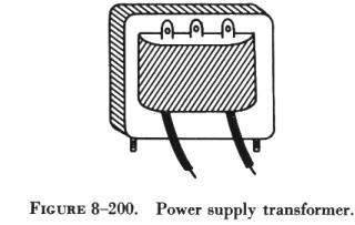
(1) Power transformers are used to step up or step down voltages and
current in many types of power supplies. They range in size from the small
power transformer shown in figure 8-200 used in a radio receiver to the
large transformers used to step down high power line voltage to the 110
- 120 volt level used in homes. |
|
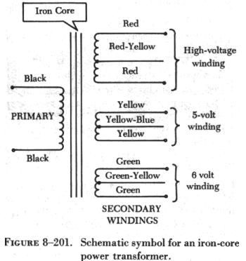 |
In figure 8-201, the schematic symbol for an iron core transformer
is shown. In this case the secondary is made up of three separate windings.
Each winding supplies a different circuit with a specific voltage, which
saves the weight, space, and expense of three separate transformers. Each
secondary has a midpoint connection, called a "center tap," which provides
a selection of half the voltage across the whole winding. The leads from
the various windings are color coded by the manufacturer, as labeled in
figure 8-201. This is a standard color code, but other codes or numbers
may be used.
(2) Audio transformers resemble power transformers. They have only one
secondary and are designed to operate over the range of audio frequencies
(20 to 20,000 cps).
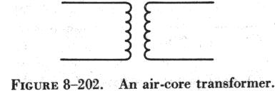
(3) RF transformers are designed to operate in equipment that functions
in the radio range of frequencies. The symbol for the RF transformer is
the same as for an RF choke coil. It has an air core as shown in figure
8-202.
|
(4) Autotransformers are normally used in power circuits; however, they
may be designed for other uses. Two different symbols for autotransformers
used in power or audio circuits are shown in figure 8-203. If used in an
RF communication or navigation circuit (B of figure
8-203), it is the same, except there is no symbol for an iron core.
The autotransformer uses part of a winding as a primary; and, depending
on whether it is step up or step down, it uses all or part of the same
winding as the secondary. For example, the autotransformer shown in A of
figure 8-203 could use the following possible choices
for primary and secondary terminals.
Current Transformers
Current transformers are used in ac power supply systems to sense generator
line current and to provide a current, proportional to the line current,
for circuit protection and control devices.
The current transformer is a ring-type transformer using a current carrying
power lead as a primary (either the power lead or the ground lead of the
ac generator). The current in the primary induces a current in the secondary
by magnetic induction.
The sides of all current transformers are marked "H1" and "H2" on the
unit base. The transformers must be installed with the "H1" side toward
the generator in the circuit in order to have proper polarity. The secondary
of the transformer should never be left open while the system is being
operated; to do so could cause dangerously high voltages, and could overheat
the transformer. Therefore, the transformer output connections should always
be connected with a jumper when the transformer is not being used but is
left in the system.
Transformer Losses
In addition to the power loss caused by imperfect coupling, transformers
are subject to "copper" and "iron" losses. Copper loss is caused by the
resistance of the conductor comprising the turns of the coil. The iron
losses are of two types called hysteresis loss and eddy current loss. Hysteresis
loss is the electrical energy required to magnetize the transformer core,
first in one direction and then in the other, in step with the applied
alternating voltage. Eddy current loss is caused by electric currents (eddy
currents) induced in the transformer core by the varying magnetic fields.
To reduce eddy current losses, cores are made of laminations coated with
an insulation, which reduces the circulation of induced currents.
Power in Transformers
Since a transformer does not add any electricity to the circuit but
merely changes or transforms the electricity that already exists in the
circuit from one voltage to another, the total amount of energy in a circuit
must remain the same. If it were possible to construct a perfect transformer,
there would be no loss of power in it; power would be transferred undiminished
from one voltage to another.
Since power is the product of volts times amperes, an increase in voltage
by the transformer must result in a decrease in current and vice versa.
There cannot be more power in the secondary side of a transformer than
there is in the primary. The product of amperes times volts remains the
same.
The transmission of power over long distances is accomplished by using
transformers. At the power source the voltage is stepped up in order to
reduce the line loss during transmission. At the point of utilization,
the voltage is stepped down, since it is not feasible to use high voltage
to operate motors, lights, or other electrical appliances.
Connecting Transformers in AC Circuits
Before studying the various means of connecting transformers in ac circuits,
the differences between single phase and three phase circuits must be clearly
understood. In a single phase circuit the voltage is generated by one alternator
coil. This single phase voltage may be taken from a single phase alternator,
or from one phase of a three phase alternator, as explained later in the
study of ac generators.
In a three phase circuit three voltages are generated by an alternator
with three coils so spaced within the alternator that the three voltages
generated are equal but reach their maximum values at different times.
In each phase of a 400 cycle, three phase generator, a cycle is generated
every 1/400 second.
In its rotation, the magnetic pole passes one coil and generates a maximum
voltage; one-third cycle (1/1200 second) later, this same pole passes another
coil and generates a maximum voltage in it; and the next one-third cycle
later, it passes still another coil and generates a maximum voltage in
it. This causes the maximum voltages generated in the three coils always
to be one-third cycle (1/1200 second) apart.
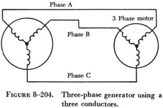
| The early three phase generators were connected to their
loads with six wires and all six leads in the circuit carried the current.
Later, experiments proved that the generator would furnish as much power
with the coils connected so that only three wires were needed for all three
phases as shown in figure 8-204. The use of three wires is standard for
the transmission of three phase power today. The return current from any
one alternator coil always flows back through the other two wires in the
three phase circuit.
Three phase motors and other three phase loads are connected with their
coils or load elements arranged so that three transmission lines are required
for delivery of power. Transformers that are used for stepping the voltage
up or down in a three phase circuit are electrically connected so that
power is delivered to the primary and taken from the secondary by the standard
three wire system. |
|
 |
|
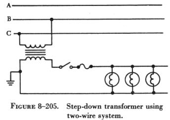
However, single phase transformers and single phase lights and motors
may be connected across any one phase of a three phase circuit, as shown
in figure 8-205. When single phase loads are connected to three phase circuits,
the loads are distributed equally among the three phases in order to balance
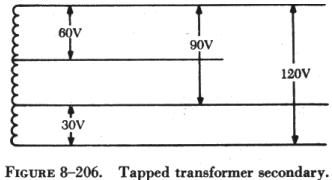
the loads on the three generator coils. Another use of the transformer
is the single phase transformer with several taps in the secondary. With
this type of transformer, the voltage can be lowered to provide several
working voltages, as shown in figure 8-206.
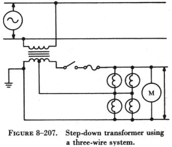
| A center tapped transformer, powering a motor requiring
220 volts along with four lights requiring 110 volts, is shown in figure
8-207. The motor is connected across the entire transformer output, and
the lights are connected from the center tap to one end of the transformer.
With this connection only half of the secondary output is used.
This type of transformer connection is used extensively on aircraft
because of the combinations of voltages that can be taken from one transformer.
Various voltages can be picked off the secondary winding of the transformer
by inserting taps (during manufacture) at various points along the secondary
windings.
The various amounts of voltage are obtained by connecting to any two
taps or to one tap and either end. |
|
Transformers for three phase circuits can be connected in any one of
several combinations of the wye (y) and delta (D) connections. The connection
used depends on the requirements for the transformer.
When the wye connection is used in three phase transformers, a fourth
or neutral wire may be used. The neutral wire connects single phase equipment
to the transformer. Voltages (115v) between any one of the three phase
lines and the neutral wire can be used for power for devices such as lights
or single phase motors.
In combination, all four wires can furnish power at 208 volts, three
phase, for operating three phase equipment, such as three phase motors
or rectifiers. When only three phase equipment is used, the ground wire
may be omitted. This leaves a three phase, three wire system as illustrated
in figure 8-208.
Figure 8-209 shows the primary and secondary
with a delta connection. With this type of connection the transformer has
the same voltage output as the line voltage. Between any two phases the
voltage is 240 volts. In this type of connection, wires A, B, and C can
furnish 240 volt, three phase power for the operation of three phase equipment.
The type of connection used for the primary coils may or may not be the
same as the type of connection used for the secondary coils. For example,
the primary may be a delta connection and the secondary a wye connection.
This is called a delta-wye connected transformer. Other combinations are
delta-delta, wye-delta, and wye-wye.
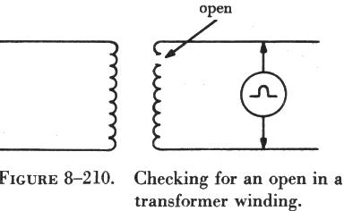
| Troubleshooting Transformers
There are occasions when a transformer must be checked for opens or
shorts, and it is often necessary to determine that a transformer is a
step up or step down transformer. An open winding in a transformer can
be located by connecting an ohmmeter as shown in figure 8-210. Connected
as shown, the ohmmeter would read infinity. If there were no open in the
coil, the ohmmeter would indicate the resistance of wire in the coil. Both
primary and secondary can be checked in the same manner. |
|
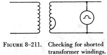 |
The ohmmeter may also be used to check for shorted windings, as shown
in figure 8-211, however, this method is not always accurate. If, for example,
the transformer had 500 turns and a resistance of 2 ohms, and 5 turns were
shorted out, the resistance would be reduced to approximately 1.98 ohms,
which is not enough of a change to be read on the ohmmeter. In this case,
the rated input voltage can be applied to the primary to permit measurement
of the secondary output voltage. If the secondary voltage is low, it can
be assumed that the transformer has some shorted windings, and the transformer
should be replaced. If the output voltage is then normal, the original
transformer can be considered defective. |
An ohmmeter can be used to determine whether a transformer is a step
up or step down transformer. In a step down transformer, the resistance
of the secondary will be less than that of the primary, and the opposite
will be true in the case of a step up transformer. Still another method
involves applying a voltage to the primary and measuring the secondary
output. The voltages used should not exceed the rated input voltage of
the primary.
If a winding is completely shorted, it usually becomes overheated because
of the high value of current flow. In many cases, the high heat will melt
the wax in the transformer, and this can be detected by the resulting odor.
Also, a voltmeter reading across the secondary will read zero. If the circuit
contains a fuse, the heavy current may cause the fuse to blow before the
transformer is heavily damaged.
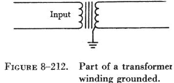
In figure 8-212 one point on a transformer winding is shown connected
to ground. If the external circuit of the transformer circuit is grounded,
a part of the winding is effectively shorted. A megger connected between
one side of the winding and the transformer case (ground) will verify this
condition with a low or zero reading. In such a case, the transformer must
be replaced.
All transformers discussed in this section are designed with one primary
winding. They operate on a single source of ac. Transformers which operate
from three voltages from an alternator, or ac generator, are called three
phase or poly phase transformers. These transformers will be discussed
in the study of generators and motors.