TUBEFORMINGPROCESSES
TUBE FORMING PROCESSES
Damaged tubing and fluid lines should be replaced with new parts whenever
possible. Sometimes replacement is impractical and repair is necessary.
Scratches, abrasions, and minor corrosion on the outside of fluid lines
may be considered negligible and can be smoothed out with a burnishing
tool or aluminum wool. Limitations on the amount of damage that can be
repaired in this manner are discussed later in this chapter under "Repair
of Metal Tube Lines." If a fluid line assembly is to be replaced, the fittings
can often be salvaged; then the repair will involve only tube forming and
replacement. Tube forming consists of four processes: (1) Cutting, (2)
bending, (3) flaring, and (4) beading. If the tubing is small and of soft
material, the assembly can be formed by hand bending during installation.
If the tubing is 1/4 inch diameter, or larger, hand bending without the
aid of tools is impractical.
Tube Cutting
| When cutting tubing, it is important to produce a square end, free
of burrs. Tubing may be cut with a tube cutter or a hacksaw. The cutter
can be used with any soft metal tubing, such as copper, aluminum, or aluminum
alloy. Correct use of the tube cutter is shown in figure 5-10.
A new piece of tubing should be cut approximately 10 percent longer
than the tube to be replaced to provide for minor variations in bending.
Place the tubing in the cutting tool, with the cutting wheel at the point
where the cut is to be made. Rotate the cutter around the tubing, applying
a light pressure to the cutting wheel by intermittently twisting the thumbscrew.
Too much pressure on the cutting wheel at one time could deform the tubing
or cause excessive burring. After cutting the tubing, carefully remove
any burrs from inside and outside the tube. Use a knife or the burring
edge attached to the tube cutter. |

|
When performing the deburring operation use extreme care that the wall
thickness of the end of the tubing is not reduced or fractured. Very slight
damage of this type can lead to fractured flares or defective flares which
will not seal properly. A fine tooth file can be used to file the end square
and smooth.
If a tube cutter is not available, or if tubing of hard material is
to be cut, use a fine tooth hacksaw, preferably one having 32 teeth per
inch. The use of a saw will decrease the amount of work hardening of the
tubing during the cutting operation. After sawing, file the end of the
tube square and smooth, removing all burrs.
| An easy way to hold small diameter tubing, when cutting
it, is to place the tube in a combination flaring tool and clamp the tool
in a vise. Make the cut about one-half inch from the flaring tool. This
procedure keeps sawing vibrations to a minimum and prevents damage to the
tubing if it is accidentally hit with the hacksaw frame or file handle
while cutting. Be sure all filings and cuttings are removed from the tube.
Tube Bending
The objective in tube bending is to obtain a smooth bend without flattening
the tube. Tubing under one-fourth inch in diameter usually can be bent
without the use of a bending tool. For larger sizes, a hand tube bender
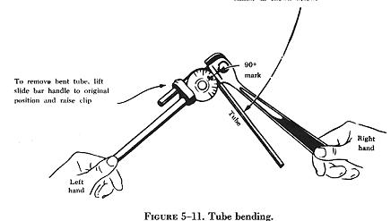
similar to that shown in figure 5-11 is usually used.
|
|
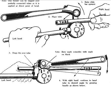
| To bend tubing with the hand tube bender, insert the tubing by raising
the slide bar handle as far as it will go. Adjust the handle so that the
full length of the groove in the slide bar is in contact with the tubing.
The zero mark on the radius block and the mark on the slide bar must align.
Make the bend by rotating the handle until the desired angle of bend is
obtained, as indicated on the radius block. |
|
Bend the tubing carefully to avoid excessive flattening, kinking, or
wrinkling. A small amount of flattening in bends is acceptable, but the
small diameter of the flattened portion must not be less than 75 percent
of the original outside diameter. Tubing with flattened, wrinkled, or irregular
bends should not be installed. Wrinkled bends usually result from trying
to bend thin wall tubing without using a tube bender. Examples of correct
and incorrect tubing bends are shown in figure 5-12.
Tube bending machines for all types of tubing are generally used in
repair stations and large maintenance shops. With such equipment, proper
bends can be made on large diameter tubing and on tubing made from hard
material. The production tube bender is an example of this type of machine.
The ordinary production tube bender will accommodate tubing ranging
from 1/2 inch to 1 1/2 inch outside diameter. Benders for larger sizes
are available, and the principle of their operation is similar to that
of the hand tube bender. The radius blocks are so constructed that the
radius of bend will vary with the tubing diameter. The radius of bend is
usually stamped on the block.
When hand or production tube benders are not available or are not suitable
for a particular bending operation, a filler of metallic composition or
of dry sand may be used to facilitate bending. When using this method,
cut the tube slightly longer than is required. The extra length is for
inserting a plug (which may be wooden) in each end.
After plugging one end, fill and pack the tube with fine, dry sand and
plug tightly. Both plugs must be tight so they will not be forced out when
the bend is made. The tube can also be closed by flattening the ends or
by soldering metal disks in them. After the ends are closed, bend the tubing
over a forming block shaped to the specified radius.
In a modified version of the filler method, a fusible alloy is used
instead of sand. In this method, the tube is filled under hot water with
a fusible alloy that melts at 160° F. The alloy filled tubing is then
removed from the water, allowed to cool, and bent slowly by hand around
a forming block or with a tube bender. After the bend is made, the alloy
is again melted under hot water and removed from the tubing.
When using either filler method, make certain that all particles of
the filler are removed so that none will be carried into the system in
which the tubing is installed. Store the fusible alloy filler where it
will be free from dust or dirt.
It can be remelted and reused as often as desired. Never heat this filler
in any other than the prescribed method, as the alloy will stick to the
inside of the tubing, making them both unusable.
Tube Flaring
Two kinds of flares are generally used in aircraft plumbing systems,
the single flare and the double flare. Flares are frequently subjected
to extremely high pressures; therefore, the flare on the tubing must be
properly shaped or the connection will leak or fail.
A flare made too small produces a weak joint, which may leak or pull
apart; if made too large it interferes with the proper engagement of the
screw thread on the fitting and will cause leakage. A crooked flare is
the result of the tubing not being cut squarely. If a flare is not made
properly, flaws cannot be corrected by applying additional torque when
tightening the fitting. The flare and tubing must be free from cracks,
dents, nicks, scratches, or any other defects.
The flaring tool used for aircraft tubing has male and female dies ground
to produce a flare of 35° to 37°. Under no circumstances is it
permissible to use an automotive type flaring tool which produces a flare
of 45°.
Single Flare
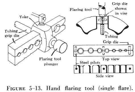
A hand flaring tool similar to that shown in figure 5-13 is used for
flaring tubing. The tool consists of a flaring block or grip die, a yoke,
and a flaring pin. The flaring block is a hinged double bar with holes
corresponding to various sizes of tubing. These holes are countersunk on
one end to form the outside support against which the flare is formed.
The yoke is used to center the flaring pin over the end of the tube to
be flared.
To prepare a tube for flaring, cut the tube squarely and remove all
burrs. Slip the fitting nut and sleeve on the tube and place the tube in
the proper size hole in the flaring tool. Center the plunger or flaring
pin over the end of the tube. Then project the end of the tubing slightly
from the top of the flaring tool, about the thickness of a dime, and tighten
the clamp bar securely to prevent slippage.
Make the flare by striking the plunger several light blows with a lightweight
hammer or mallet. Turn the plunger a half turn after each blow and be sure
it seats properly before removing the tube from the flaring tool. Check
the flare by sliding the sleeve into position over the flare. The outside
diameter of the flare should extend approximately one-sixteenth inch beyond
the end of the sleeve, but should not be larger than the major outside
diameter of the sleeve.
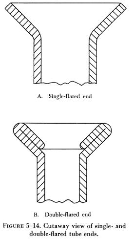
| Double Flare
A double flare should be used on 5052-O and 6061-T aluminum alloy tubing
for all sizes from 1/8 to 3/8 inch outside diameter. This is necessary
to prevent cutting off the flare and failure of the tube assembly under
operating pressures. Double flaring is not necessary on steel tubing. See
figure 5-14 for an illustration of single and double flared tubing. The
double flare is smoother and more concentric than the single flare and,
therefore, seals better. It is also more resistant to the shearing effect
of torque.
To make the double flare, separate the clamp blocks of the double flaring
tool and insert and clamp the tubing with the burred end flush with the
top of the clamp. Insert the starting pin into the flaring pin guide and
strike the pin sharply with a hammer until the shoulder of the pin stops
against the clamp blocks. Remove the starting pin and insert the finishing
pin; hammer it until its shoulder rests on the clamp block.
Beading
Tubing may be beaded with a hand beading tool, with machine beading
rolls, or with grip dies. The method to be used depends on the diameter
and wall thickness of the tube and the material from which it was made.
The hand beading tool is used with tubing having 1/4 to 1 inch outside
diameter. The bead is formed by using the beader frame with the proper
rollers attached. The inside and outside of the tube is lubricated with
light oil to reduce the friction between the rollers during beading. The
sizes, marked in sixteenths of an inch on the rollers, are for the outside
diameter of the tubing that can be beaded with the rollers. |
|
Separate rollers are required for the inside of each tubing size, and
care must be taken to use the correct parts when beading. The hand beading
tool works somewhat like the tube cutter in that the roller is screwed
down intermittently while rotating the beading tool around the tubing.
In addition, a small vise (tube holder) is furnished with the kit.
Other methods and types of beading tools and machines are available,
but the hand beading tool is used most often. As a rule, beading machines
are limited to use with large diameter tubing, over 1 15/16 inch, unless
special rollers are supplied. The grip die method of beading is confined
to small tubing.
Flareless Tube Assemblies
Although the use of flareless tube fittings eliminates all tube flaring,
another operation, referred to as presetting, is necessary prior to installation
of a new flareless tube assembly. Figure 5-15 (steps
1, 2, and 3) illustrates the presetting operation, which is performed as
follows:
(a) Cut the tube to the correct length, with the ends perfectly square.
Deburr the inside and outside of the tube. Slip the nut, then the sleeve,
over the tube (step 1).
(b) Lubricate the threads of the fitting and nut with hydraulic fluid.
Place the fitting in a vise (step 2), and hold the tubing firmly and squarely
on the seat in the fitting. (Tube must bottom firmly in the fitting.) Tighten
the nut until the cutting edge of the sleeve grips the tube. This point
is determined by slowly turning the tube back and forth while tightening
the nut. When the tube no longer turns, the nut is ready for final tightening.
(c) Final tightening depends upon the tubing. For aluminum alloy tubing
up to and including 1/2 inch outside diameter, tighten the nut from one
to one and one-sixth turns. For steel tubing and aluminum alloy tubing
over 1/2 inch outside diameter, tighten from one and one-sixth to one and
one-half turns.
After presetting the sleeve, disconnect the tubing from the fitting
and check the following points
(a) The tube should extend 3/32 to 1/8 inch beyond the sleeve pilot;
otherwise blowoff may occur.
(b) The sleeve pilot should contact the tube or have a maximum clearance
of 0.005 inch for aluminum alloy tubing or 0.015 inch for steel tubing.
(c) A slight collapse of the tube at the sleeve cut is permissible.
No movement of the sleeve pilot, except rotation, is permissible.