ULTRASONIC
ULTRASONIC TESTING
Ultrasonic detection equipment has made it possible to locate defects
in all types of materials without damaging the material being inspected.
Minute cracks, checks, and voids, too small to be seen by X-ray, are located
by ultrasonic inspection. An ultrasonic test instrument requires access
to only one surface of the material to be inspected and can be used with
either straight line or angle beam testing techniques.
Two basic methods are used for ultrasonic inspection. The first of these
methods is immersion testing. In this method of inspection, the part under
examination and the search unit are totally immersed in a liquid couplant,
which may be water or any other suitable fluid.
| The second method is called contact testing, which is readily
adapted to field use, and is the method discussed in this chapter. In this
method the part under examination and the search unit are coupled with
a viscous material, liquid or a paste, which wets both the face of the
search unit and the material under examination.
There are two basic ultrasonic systems: (1) Pulsed and (2) resonance.
The pulsed system may be either echo or through transmission; the echo
is the most versatile of the two pulse systems.
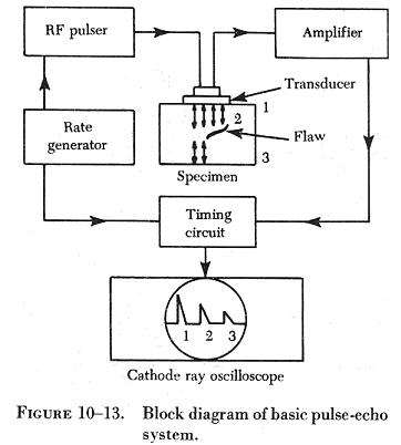
Pulse Echo
Flaws are detected by measuring the amplitude of signals reflected and
the time required for these signals to travel between specific surfaces
and the discontinuity. (See figure 10-13.)
The time base, which is triggered simultaneously with each transmission
pulse, causes a spot to sweep across the screen of the CRT (Cathode ray
tube). The spot sweeps from left to right across the face of the scope
50 to 5,000 times per second, or higher if required for high speed automated
scanning. Due to the speed of the cycle of transmitting and receiving,
the picture on the oscilloscope appears to be stationary. |
|
 |
A few microseconds after the sweep is initiated, the rate generator
electrically excites the pulser and the pulser in turn emits an electrical
pulse. The transducer converts this pulse into a short train of ultrasonic
sound waves. If the interfaces of the transducer and the specimen are properly
orientated, the ultrasound will be reflected back to the transducer when
it reaches the internal flaw and the opposite surface of the specimen.
The time interval between the transmission of the initial impulse and the
reception of the signals from within the specimen is measured by the timing
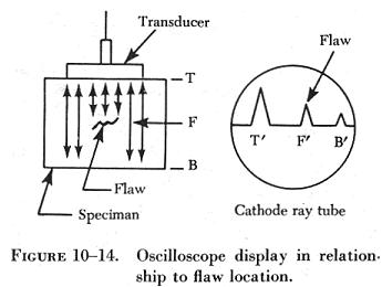
circuits. The reflected pulse received by the transducer is amplified,
then transmitted to the oscilloscope, where the pulse received from the
flaw is displayed on the CRT screen. The pulse is displayed in the same
relationship to the front and back pulses as the flaw is in relation to
the front and back surfaces of the specimen. (See figure 10-14.) |
The Reflectoscope is a pulse echo type instrument. The Reflectoscope
can be used for the detection of defects such as cracks, folds, inclusions,
delaminations, partial welds, voids, shrinks, porosity, flaking, and other
subsurface defects.
The principle of operation is pictured in figure
10-15, where electrical pulses are transformed by the crystal into
ultrasonic vibrations which are transmitted into the material. The portion
of the electrical pulse delivered to the cathode ray tube causes an initial
pulse indication, as shown in figure 10-15, view
A. The back reflection has formed in view B, the vibrations having traveled
to the bottom of the part and reflected back to the searching unit, which
transforms them back into electrical pulses. The screen's vertical indication
of their return is known as the "first back reflection indication." If
a defect is present (figure 10-15, view C), a portion
of the vibrations traveling through the material is reflected from the
defect, causing an additional indication on the screen. The horizontal
sweep travel indicates the time elapsed since the vibrations left the crystal.
This type of operation, referred to as straight beam testing, is suitable
for the detection of flaws whose planes are parallel to the plane of the
part. By means of angle beam testing, also referred to as shear wave testing,
the usefulness of the Reflectoscope includes the following:
1. Flaws whose planes lie at an angle to the plane of the part.
2. Discontinuities in areas that cannot be reached with the standard
straight beam technique.
3. Some internal defects in plate and sheet stock.
4. Some types of internal defects in tubing, pipe and bar stock, such
as inclusions and small cracks near the surface.
5. Cracks in parent metal resulting from welding.
6. Some defects in welds.
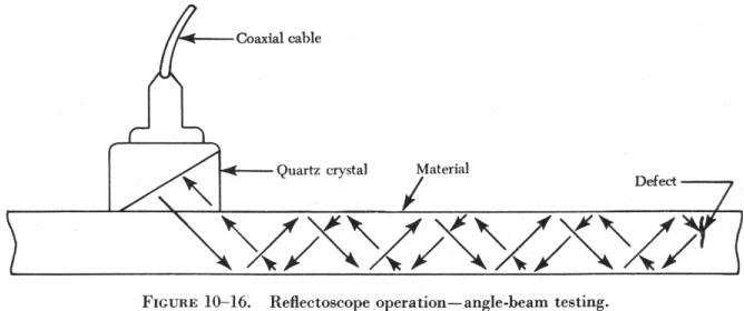
Angle beam testing differs from straight beam testing only in the manner
in which the ultrasonic waves pass through the material being tested. As
shown in figure 10-16, the beam is projected into the material at an acute
angle to the surface by means of a crystal cut at an angle and mounted
in plastic. The beam or a portion thereof reflects successively from the
surfaces of the material or any other discontinuity, including the edge
of the piece. In straight beam testing, the horizontal distance on the
screen between the initial pulse and the first back reflection represents
the thickness of the piece; while in angle beam testing, this distance
represents the width of the material between the s earching unit and the
opposite edge of the piece.
Resonance System
This system differs from the pulse method in that the frequency of transmission
is, or can be, continuously varied. The resonance method is principally
used for thickness measurements when the two sides of the material being
tested are smooth and parallel. The point at which the frequency matches
the resonance point of the material being tested is the thickness determining
factor.
It is necessary that the frequency of the ultrasonic waves, corresponding
to a particular dial setting, be accurately known. Checks should be made
with standard test blocks to guard against possible drift of frequency.
If the frequency of an ultrasonic wave is such that its wavelength is
twice the thickness of a specimen (fundamental frequency), then the reflected
wave will arrive back at the transducer in the same phase as the original
transmission so that strengthening of the signal, or a resonance, will
occur. If the frequency is increased so that three times the wavelength
equals four times the thickness, then the reflected signal will return
completely out of phase with the transmitted signal and cancellation will
occur. Further increase of the frequency, so that the wavelength is equal
to the thickness again, gives a reflected signal in phase with the transmitted
signal and resonance occurs once more.
By starting at the fundamental frequency and gradually increasing the
frequency, the successive cancellations and resonances can be noted and
the readings used to check the fundamental frequency reading. (See figure
10-17.)
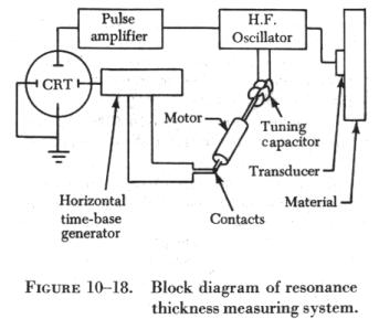
| In some instruments, the oscillator circuit contains a motor driven
capacitor which changes the frequency of the oscillator. (See figure 10-18.)
In other instruments, the frequency is changed by electronic means.
The change in frequency is synchronized with the horizontal sweep of
a CRT. The horizontal axis thus represents a frequency range. If the frequency
range contains resonances, the circuitry is arranged to present these vertically.
Calibrated transparent scales are then placed in front of the tube, and
the thickness can be read directly. The instruments normally operate between
0.25 mc. and 10 mc. in four or five bands.
The resonant thickness instrument can be used to test the thickness
of such metals as steel, cast iron, brass, nickel, copper, silver, lead,
aluminum, and magnesium. In addition, areas of corrosion or wear on tanks,
tubing, airplane wing skins, and other structures or products can be located
and evaluated. |
 |
Direct reading, dial operated units are available that measure thickness
between 0.025 inch and 3 inches with an accuracy of better than ±1
percent.
Ultrasonic inspection requires a skilled operator who is familiar with
the equipment being used as well as the inspection method to be used for
the many different parts being tested.