VOLTAGEDIVIDERS VOLTAGE DIVIDERS
 
Voltage dividers are devices which make it possible to obtain more than one voltage from a single power source.

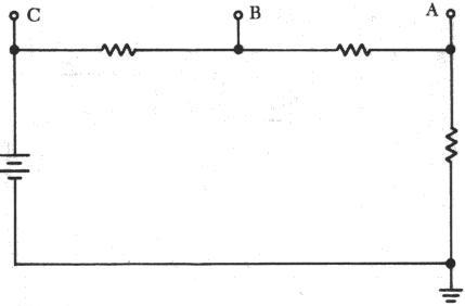
A voltage divider usually consists of a resistor, or resistors connected in series, with fixed or movable contacts and two fixed terminal contacts. As current flows through the resistor, different voltages can be obtained between the contacts. A typical voltage divider is shown in figure 8-72.

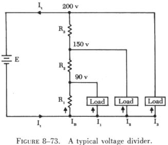
A load is any device which draws current. A heavy load means a heavy current drain. In addition to the current drawn by the various loads, there is a certain amount drawn by the voltage divider itself. This is known as bleeder current.

Figure 8-72 Voltage dividers cuircuit

 
To understand how a voltage divider works, examine the illustration in figure 8-73 carefully and observe the following:

Each load draws a given amount of current: I1, I2, I3. In addition to the load currents, some bleeder current (IB) flows. The current (It) is drawn from the power source and is equal to the sum of all currents.

The voltage at each point is measured with respect to a common point. Note that the common point is the point at which the total current (It) divides into separate currents (I1, I2, I3).

Each part of the voltage divider has a different current flowing in it. The current distribution is as follows:

Through R1 - bleeder current (IB)
Through R2 - IB plus I1
Through R3 - IB PIUS I1, plus I2

The voltage across each resistor of the voltage divider is:

90 volts across R1
60 volts across R2
50 volts across R3
 
The voltage divider circuit discussed up to this point has had one side of the power supply (battery) at ground potential. In figure 8-74 the common reference point (ground symbol) has been moved to a different point on the voltage divider. The voltage drop across R1 is 20 volts; however, since tap A is connected to a point in the circuit that is at the same potential as the negative side of the battery, the voltage between tap A and the reference point is a negative (-) 20 volts. Since resistors R2 and R3 are connected to the positive side of the battery, the voltages between the reference point and tap B or C are positive.

A simple method of determining negative and positive voltages is provided by the following rules: 


Figure 8-74 Positive and Negative on a voltages divider

 
(1) If current enters a resistance flowing away from the reference point, the voltage drop across that resistance is positive in respect to the reference point; 

(2) if current flows out of a resistance toward the reference point, the voltage drop across that resistance is negative in respect to the reference point. It is the location of the reference point that determines whether a voltage is negative or positive.

Tracing the current flow provides a means for determining the voltage polarity. Figure 8-75 shows the same circuit with the polarities of the voltage drops and the direction of current flow indicated.

Figure 8-75 Current flow through a voltage divider

 
The current flows from the negative side of the battery to R1. Tap A is at the same potential as the negative terminal of the battery since the slight voltage drop caused by the resistance of the conductor is disregarded; however, 20 volts of the source voltage are required to force the current through R1 and this 20 volt drop has the polarity indicated. Stated another way, there are only 80 volts of electrical pressure left in the circuit on the ground side of R1.

When the current reaches tap B, 30 more volts have been used to move the electrons through R2, and in a similar manner the remaining 50 volts are used for R3. But the voltages across R2 and R3 are positive voltages, since they are above ground potential.

Figure 8-76 shows the voltage divider used previously. The voltage drops across the resistances are the same; however, the reference point (ground) has been changed. The voltage between ground and tap A is now a negative 100 volts, or the applied voltage. The voltage between ground and tap B is a negative 80 volts, and the voltage between ground and tap C is a negative 50 volts.