VOLTMETERS
| VOLTMETERS
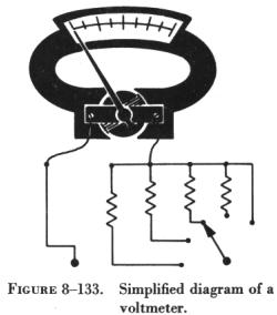
The D'Arsonval meter movement can be used either as an ammeter or a
voltmeter (figure 8-133). Thus, an ammeter can be converted to a voltmeter
by placing a resistance in series with the meter coil and measuring the
current flowing through it. In other words, a voltmeter is a current measuring
instrument, designed to indicate voltage by measuring the current flow
through a resistance of known value. Various voltage ranges can be obtained
by adding resistors in series with the meter coil. For low range instruments,
this resistance is mounted inside the case with the D'Arsonval movement
and usually consists of resistance wire having a low temperature coefficient
which is wound either on spools or card frames. For higher voltage ranges,
the series resistance may be connected externally. When this is done, the
unit containing the resistance is commonly called a multiplier. |
|
Extending the Voltmeter Range
The value of the necessary series resistance is determined by the current
required for full scale deflection of the meter and by the range of voltage
to be measured. Because the current through the meter circuit is directly
proportional to the applied voltage, the meter scale can be calibrated
directly in volts for a fixed series resistance.
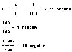
For example, assume that the basic meter (microammeter) is to be made
into a voltmeter with a full scale reading of 1 volt. The coil resistance
of the basic meter is 100 ohms, and 0.0001 ampere (100 microamperes) causes
a full scale deflection. The total resistance, R, of the meter coil and
the series resistance is

and the series resistance alone is

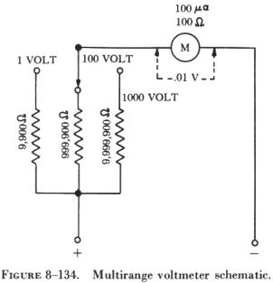
| Multirange voltmeters utilize one meter movement with the
required resistances connected in series with the meter by a convenient
switching arrangement. A multirange voltmeter circuit with three ranges
is shown in figure 8-134. The total circuit resistance for each of the
three ranges beginning with the 1 volt range is:
|
|
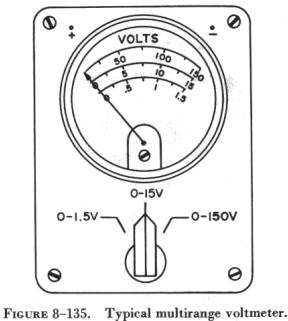 |
Multirange voltmeters, like multirange ammeters, are used frequently.
They are physically very similar to ammeters, and their multipliers are
usually located inside the meter with suitable switches or sets of terminals
on the outside of the meter for selecting ranges (see figure 8-135).
Voltage measuring instruments are connected across (in parallel with)
a circuit. If the approximate value of the voltage to be measured is not
known, it is best, as in using the ammeter, to start with the highest range
of the voltmeter and progressively lower the range until a suitable reading
is obtained.
In many cases, the voltmeter is not a central zero indicating instrument.
Thus, it is necessary to observe the proper polarity when connecting the
instrument to the circuit, as is the case when connecting the dc ammeter.
The positive terminal of the voltmeter is always connected to the positive
terminal of the source, and the negative terminal to the negative terminal
of the source, when the source voltage is being measured. In any case,
the voltmeter is connected so that electrons will flow into the negative
terminal and out of the positive terminal of the meter. In figure
8-136 a multimeter is properly connected to a circuit to measure the
voltage drop across a resistor. The function switch is set at the dc volts
position and the range switch is placed in the 50 volt position. |
The function of a voltmeter is to indicate the potential difference
between two points in a circuit. When the voltmeter is connected across
a circuit, it shunts the circuit. If the voltmeter has low resistance,
it will draw an appreciable amount of current. The effective resistance
of the circuit will be lowered, and the voltage reading will consequently
be lowered.
When voltage measurements are made in high resistance circuits, it is
necessary to use a high resistance voltmeter to prevent the shunting action
of the meter. The effect if less noticeable in low resistance circuits
because the shunting effect is less.
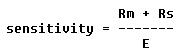
Voltmeter Sensitivity
The sensitivity of a voltmeter is given in ohms per volt (ohms/E) and
is determined by dividing the resistance (Rm) of the meter plus the series
resistance (Rs) by the full scale reading in volts. Thus,
This is the same as saying that the sensitivity is equal to the reciprocal
of the current (in amperes); that is,
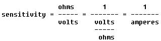
Thus, the sensitivity of a 100 microampere movement is the reciprocal
of 0.0001 ampere, or 10,000 ohms per volt.
The sensitivity of a voltmeter can be increased by increasing the strength
of the permanent magnet, by using lighter weight materials for the moving
element (consistent with increased number of turns on the coil), and by
using sapphire jewel bearings to support the moving coil.
Voltmeter Accuracy
The accuracy of a meter is generally expressed in percent. For example,
a meter with an accuracy of 1 percent will indicate a value within 1 percent
of the correct value. The statement means that, if the correct value is
100 units, the meter indication may be anywhere within the range of 99
to 101 units.