The Federal airways network is based upon the electronic aids already discussed. The navigation system has three component parts: the pilot, the airborne receiver, and the ground navigation facility. When the recognized errors which each contributes are considered, a total system accuracy can be determined. When this accuracy is applied, the area in which obstruction clearance should be provided becomes apparent. Inherent in this concept is the premise that the pilot fly, as closely as possible, the prescribed courses and altitudes.
Obstruction clearance criteria are based on the airborne receiver contributing not more than ±4.2° error to the total system error. Pilot performance must assure a tracking accuracy within ±2.5° (quarter scale) needle deflection. Where these standards are not assured by the pilot, the safety and accuracy normally provided by the criteria are impaired. The VOR and VORTAC facilities are the foundation of the system. Connecting these facilities is the network of routes forming the Victor Airway and Jet Route Systems.
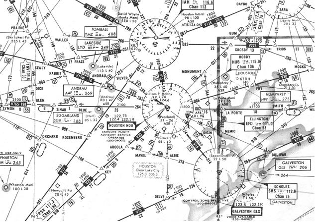
Each Federal Airway is based on a centerline that extends from one navigation aid or intersection to another navigation aid (or through several navigation aids or intersections) specified for that airway. The infinite number of radials transmitted by the VOR permits 360 possible separate airway courses to or from the facility, one for each degree of azimuth. Thus, a given VOR located within approximately 100 miles of several other VORs may be used to establish a number of different airways. For example, 8 radials at Humble VORTAC define 10 low altitude airways (Fig. 10-3).
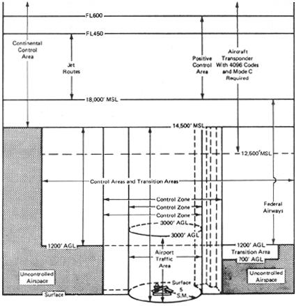
Three route systems have been established for air navigation purposes: (1) Victor Airway System, (2) Jet Route System, and (3) Area Navigation (RNAV) Route System. The Victor Airway System consists of airways designated from 1,200 feet above the surface (or in some instances higher) to but not including 18,000 feet MSL. The jet Route System consists of jet routes established from 18,000 feet MSL to FL 450. The RNAV Route System presently consists of a structure of approximately 76 high altitude routes (18,000 feet MSL to FL 450) embracing the 48 contiguous states. The airspace above FL 450 is for point-to-point operation.
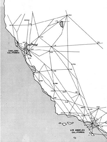
Figure 10-2. Navaids during the 1960's.
|
Figure 10-3. VOR radials and airways.
 |
To the extent possible, these route systems have been aligned
in an overlying manner to facilitate transition between each. At certain
airports, Standard Terminal Arrival Routes (STARs) have been established
for application to arriving IFR aircraft.
Like highways, Victor airways are designated by number - generally
north/south airways are odd; east/west airways are even. When airways coincide
on the same radial, the airway segment shows the numbers of all the airways
on it. For example, the Humble 290 radial in the chart excerpt (Fig. 10-3),
defines three airways V15-306S-477W.
Alternate Victor Airways are used for lateral separation when traffic conditions require it, or as "one-way" routes for efficient control of traffic flow to and from terminal areas. For example, V-14 serves as a normal arrival route into Oklahoma City from Tulsa, Oklahoma. V-14N, lying to the north of V-14, is an alternate arrival route from Tulsa. V-14S, to the south of V-14, is a normal departure route from Oklahoma City.
Preferred IFR Routes have been established between major terminals to guide pilots in planning their routes of flight, to minimize route changes, and to aid in the orderly management of air traffic in Federal airways. Both high- and low-altitude preferred routes are listed in the Airport/Facility Directory.
Terminal Routes (Standard Terminal Arrival Routes [STARs] and Standard Instrument Departures [SIDs]) - These Standard Routes have been established and published as an air traffic control aid in certain complex terminal areas. They help reduce verbiage on clearance delivery and control frequencies and provide the pilot with a description of terminal routing. Both SIDs and STARs are currently published in National Ocean Survey booklets. Instructions for pilot use of these coded routes are contained in the Airman's Information Manual. Certain complex terminal areas are covered by Area Charts.
Figure 10-4. Controlled airspace.
 |