Considerations of safety, users needs, and volume of flight operations are some of the factors which have dictated the establishment of controlled airspace. Such airspace includes the Continental Control Area, Control Areas, Control Zones, Terminal Control Areas, and Transition Areas. Figure 10-4 is a three dimensional portrayal of certain features of the airspace structure.
It is essential that you, as an instrument pilot, be well informed regarding the various airspace segments. Refer to the Airman's Information Manual for current information.
Radio Navigation Charts
Radio navigation data are shown on many types of aeronautical charts, including the Sectional and WAC charts familiar to the VFR pilot. More specialized charts, compiled and printed by the National Ocean Survey, include several types for use by the instrument pilot.
Standard Instrument Departure (SID) Charts are designed to expedite clearance delivery and to facilitate transition between takeoff and enroute operations. These charts, published in two bound booklets, provide departure routing clearance in graphic and textual form. Standard Terminal Arrival Route (STAR) Charts are designed to expedite air traffic control arrival route procedures and to facilitate transition between enroute and instrument approach operations. These charts, published in one bound booklet, provide arrival route procedures in graphic and textual form. Enroute Low Altitude Charts provide aeronautical information for enroute navigation (IFR) in the low altitude stratum. Area Charts, which are part this series, furnish terminal data in a larger scale in congested areas. Enroute High Altitude Charts provide aeronautical information for enroute instrument navigation (IFR) in the high altitude stratum. Instrument Approach Procedure Charts portray the aeronautical data which is required to execute instrument approaches to airports. Each procedure is designed for use with a specific type of electronic navigational aid. These charts reflect the criteria associated with the U.S. Standards for Terminal Instrument Approach Procedures (TERPs). Detailed information regarding their use is contained in Advisory Circular 90-1A, Civil Use of U.S. Government Instrument Approach Procedure Charts, which is reproduced in the following pages of this chapter. Regarding helicopter minimums, FAR 97.3(d-1) states, "Helicopters may also use ... the Category A minimum descent altitude (MDA) or decision height (DH). The required visibility minimum may be reduced to one-half the published visibility minimum for Category A aircraft, but in no case may it be reduced to less than one-quarter mile or 1,200 feet RVR."
CIVIL USE OF U.S. GOVERNMENT INSTRUMENT APPROACH PROCEDURE CHARTS
(Reproduced from AC 90-1A)
1. APPLICATION. Civil Instrument Approach Procedures are established
by the Federal Aviation Administration after careful analysis of obstructions,
terrain features and navigational facilities. Narrative type procedures
authorized by the FAA are published in the Federal Register as rule making
action under Federal Aviation Regulations, Part 97. Based on this information,
the U.S. Coast and Geodetic Survey, and other charting agencies, publish
instrument approach charts as a service to the instrument pilot. FAR 91.116(a)
{§ 91.116 recodified to § 91.175} requires use of specified procedures
by all pilots approaching for landing under Instrument Flight Rules. Appropriate
maneuvers, which include altitudes, courses, and other limitations, are
prescribed in these procedures. They have been established for safe letdown
during instrument flight conditions as a result of many years of accumulated
experience. It is important that all pilots thoroughly understand these
procedures and their use.
2. DEFINITIONS.
a. MDA - "Minimum descent altitude" means the lowest altitude,
expressed in feet above mean sea level, to which descent is authorized
on final approach, where no electronic glide slope is provided, or during
circle-to-land maneuvering in execution of a standard instrument approach
procedure.
b. DH - "Decision height", with respect to the operation of aircraft,
means the height at which a decision must be made, during an ILS or PAR
instrument approach, to either continue the approach or to execute a missed
approach. This height is expressed in feet above mean sea level (MSL),
and for Category II ILS operation the decision height is additionally expressed
as a radio altimeter setting.
c. HAA - "Height above airport" indicates the height of the MDA
above the published airport elevation. HAA is published in conjunction
with circling minimums for all types of approaches.
d. HAT - "Height above touchdown" indicates the height of the
DH or MDA above the highest runway elevation in the touchdown zone (first
3,000 feet of runway). HAT is published in conjunction with straight-in
minimums.
e. NoPT - means No Procedure Turn Required.
f. "Precision approach procedure" means a standard instrument
approach in which an electronic glide slope is provided (ILS OR PAR).
g. "Non-precision approach procedure" means a standard instrument
approach in which no electronic glide slope is provided.
h. Instrument Approach Procedure. An instrument approach procedure
is one that is prescribed and approved for a specific airport by competent
authority and published in an acceptable aeronautical information publication.
(1) U.S. Civil Standard Instrument Approach Procedures are approved
by the FAA as prescribed under FAR Part 97 and are published in the Federal
Register. For the convenience of the user, the aeronautical data prescribed
in standard instrument approach procedures are portrayed on instrument
approach procedure charts and may be obtained from Coast and Geodetic Survey
and other publishers of aeronautical charts.
(2) U.S. Military Standard Instrument Approach Procedures are
established and published by the Department of Defense and are contained
in the DOD Flight Information Publication (FLIP). Civilian requests for
military procedures should be directed to the Coast and Geodetic Survey,
Washington Science Center, Attn: Distribution Division, Rockville, Maryland
20852.
(3) Special Instrument Approach Procedures are approved by the
FAA for individual operators and are not published in FAR Part 97 for public
use.
(4) Foreign Country Standard Instrument Approach Procedures
are established and published as contained in that country's accepted Aeronautical
Information Publication (AIP).
3. DISCUSSION OF MAJOR CHANGES.
a. Minimum Descent Altitude (MDA)/Decision Height (DH) Concept.
(1) IFR Landing Minimums. FAR sections 91.116 {§ 91.116
recodified to § 91.175} and 91.117, {§ 91.117 was deleted when
part 91 was recodified} effective November 18, 1967, contain new rules
applicable to landing minimums. Ceiling minimums are no longer prescribed
in approach procedures as a landing limit. The published visibility is
the required weather condition for landing as prescribed in FAR 91.116(b)
{§ 91.116 recodified to § 91.175}. FAR 91 now allows approach
down to the prescribed minimum descent altitude (MDA) or decision height
(DH), as appropriate to the procedure being executed, without regard to
reported ceiling.
(2) Descent Below MDA or DH. No person may operate an aircraft
below the prescribed minimum descent altitude or continue an approach below
the decision height unless -
(a) The aircraft is in a position from which a normal
approach can be made to the runway of intended landing; and
(b) The approach threshold of that runway, or approach
lights or other markings identifiable with the approach end of that runway,
is clearly visible to the pilot.
(c) If, upon arrival at the missed approach point, or
at any time thereafter, any of the above requirements are not met, the
pilot shall immediately execute the appropriate missed approach procedure.
Note: The former FAR authorization to descend 50 feet
below the applicable minimum landing altitude when clear of clouds is eliminated.
(3) Conversion of Ceiling MDA or DH. Effective November 18,
1967, the Federal Aviation Regulations were amended to provide that if
the landing minimums in the instrument approach procedure are stated in
terms of ceiling and visibility, the visibility minimum is the applicable
landing minimum as prescribed in FAR 91.116(b) {§ 91.116 recodified
to § 91.175}. A ceiling minimum shall be added to the field elevation,
and that value is observed as the MDA or DH as appropriate to the procedure
being executed.
(4) Publication of Landing Minimums. The new Government-produced
charts always contain the following information listed in this order: MDA
or DH, visibility, HAA or HAT, and military minimums (ceiling and visibility)
for each aircraft approach category.
Note: Since the chart is used by both civil and military
pilots, the ceiling, as well as visibility, required by the military will
be published in parentheses. Civil operators should disregard this information.
(a) Following are Examples of Published Landing Minimums.
(Extracted from sample chart Figure 5.)
1 Straight-in Precision. An example of straight-in
ILS minimums is shown below. The touchdown zone elevation is 965 feet,
whereas the airport elevation is 983 feet.
STRAIGHT-IN
TO RUNWAY 14
DH VIS HAT
MILITARY
S-ILS 14
1165 / 24 200
(200-1/2)
It
should be noted that the visibility is separated from the DH by a slant
line (/) when it is RVR, and separated by a hyphen (-) when it is meteorological
visibility. This will help differentiate the two visibility values. RVR
is indicated in 100's of feet, and meteorological visibility is in statute
miles. If RVR were not authorized, it would appear 1165-1/2.
2 Straight-in Non-precision. When the ILS approach
procedure is used but the aircraft does not have a glide slope receiver
or the glide slope ground equipment is out of service, localizer minimums
apply to the straight-in landing on that runway.
MDA VIS HAT
MILITARY
S-LOCALIZER 14
1500 / 24 535
(600-1/2)
3 Circling. Visibility for circling is always in a meteorological value of statute miles. Height of the MDA above the airport elevation is provided by HAA.
MDA VIS HAA
MILITARY
Circling
1640 - 1 657
(700-1)
b. Standard Take-off Minimums. FAR 91.116(c) {§ 91.116 recodified
to § 91.175} prescribes take-off rules for FAR 121, 129, and 135 operators
and establishes standard take-off visibility minimums as follows:
(1) Aircraft having two engines or less - one statute mile.
(2) Aircraft having more than two engines - one-half statute
mile.
In cases where departure procedures or non-standard take-off
minimums are prescribed, a symbol is shown on the chart indicating
that the separate listing should be consulted. See figures 5, 13, and 17.
Ceiling minimums are no longer prescribed for take-off except for those
runways where a ceiling minimum is required to enable the pilot to see
and avoid obstructions. The ceiling and visibility minimums previously
prescribed apply until individual procedures are reissued under the new
criteria.
c. Standard Alternate Minimums. Alternate minimums specified
for an instrument approach procedure continue to require both ceiling and
visibility minimums. FAR 91.83 {§ 91.83 recodified to § 91.153}
establishes standard IFR alternate minimums as follows:
(1) Precision approach procedure: ceiling 600 feet and visibility
- two statute miles.
(2) Non-precision approach procedure: ceiling 800 feet and visibility
- two statute miles.
The standard IFR alternate minimums apply unless higher minimums
are specified for the procedure used. These are denoted by a symbol
on the chart indicating that the separate listing should be consulted.
See figures 6, 14, and 18.
d. Inoperative Components, Visual Aids, and Adjustment of Landing
Minimums.
(1) Components and Visual Aids.
(a) Precision Approach Procedure. ILS (Instrument Landing
System) basic components are localizer, glide slope, outer marker and middle
marker. PAR (Precision Approach Radar) basic components are azimuth, range,
and elevation information.
The following visual aids may supplement the ILS
or PAR, and may provide lower visibility minimums:
ALS - Approach Lighting System, 3000' of Standard High Intensity Lights
with Sequence Flashers.
SALS - Short Approach Lighting System, 1500' of Standard ALS.
SSALR - Simplified Short Approach Lighting System (1400' of High Intensity
Light Bars) plus 1600' of runway Alignment Indicator Lights (RAIL - Sequence
Flashers).
MALSR - Medium Intensity Lighting of Simplified Short Approach Lighting
System (1400' of Medium Intensity Light Bars) plus 1600' of Runway Alignment
Indicator Lights (RAIL - Sequence Flashers).
TDZL - Touchdown Zone Lights.
RCLS - Runway Centerline Light System.
HIRL - High Intensity Runway Edge Lights.
MIRL - Medium Intensity Runway Edge Lights.
(b) Non-precision Approach Procedures.
The basic component is the facility providing course
guidance, i.e., VOR, NDB, etc. In the case of VOR/DME type procedures,
basic components are the VOR and DME facilities.
All of the visual aids listed under precision approach
procedures may supplement non-precision procedures plus the following:
MALS - Medium Intensity Approach Light System. Total 1400'.
RAIL - Runway Alignment Indicator Light.
REIL - Runway End Identifier Lights.
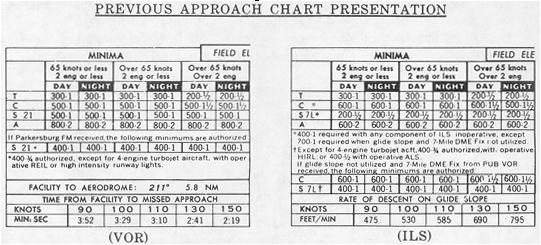
(2) Previous Approach Charts (Old Chart Format). In many cases,
minimums lower than those authorized in the straight-in line are authorized
when lighting aids such as REIL, ALS, etc., are installed for the landing
runway. Also, minimums higher than those authorized in its straight-in
line are required when certain components of an ILS system are inoperative.
This information concerning minimums is published as notes below the minimums
section. (Figure 1.)
Figure 1.
|
(3) Inoperative Components or Visual Aids Table (Pertaining to
new Chart Format).
(a) Since all air navigation facilities have a very low
out-of-service time, the lowest landing minimums with all components and
visual aids operating are published.
To determine landing minimums when components or aids
of the system are inoperative or are not utilized, inoperative components
or visual aids tables are published and appear on a separate sheet for
insertion in the approach chart binders. This method was selected to reduce
chart clutter.
Figure 2.
INOPERATIVE COMPONENTS OR VISUAL AIDS TABLE
1 ILS and PAR with visibility of 1/2 mile (RVR 2400) or greater.
Inoperative Increase Increase Approach
Component or Aid DH Visibility Category
OM*, MM* 50 feet By None ABC
OM*, MM* 50 feet By 1/4 mile D
ALS 50 feet By 1/4 mile ABCD
SALS 50 feet By 1/4 mile ABC
*Not applicable to PAR
2 ILS and PAR with visibility minimum of 1,800 or 2,000 feet RVR.
Inoperative Increase Increase Approach
Component or Aid DH Visibility Category
OM*, MM* 50 feet To 1/2 mile ABC
OM*, MM* 50 feet To 3/4 mile D
ALS 50 feet To 3/4 mile ABCD
HIRL, TDZL, RCLS None To 1/2 mile ABCD
RVR None To 1/2 mile ABCD
*Not applicable to PAR
3 VOR, VOR/DME, LOC, LDA, and ASR.
Inoperative Increase Increase Approach
Visual Aid MDA Visibility Category
ALS, SALS None By 1/2 mile ABC
HIRL, MALS, REILS None By 1/4 mile ABC
4 NDB (ADF) and RNG.
Inoperative Increase Increase Approach
Visual Aid MDA Visibility Category
ALS None By 1/4 mile ABC
5 LOC Approaches
Inoperative Increase Increase Approach
Component or Aid MDA Visibility Category
ALS, MM None By 1/4 mile D
(b) Application of the Inoperative Components or Visual
Aids Table. When using the revised approach charts, the minimums must be
adjusted in accordance with the inoperative component or visual aids table.
This will be done when a ground component or visual aid pertinent to the
procedure is inoperative or not utilized.
With two or more components inoperative, only the greater
or greatest increase in altitude or visibility is required; and the increases
are not cumulative.
When a visual aid has been installed, but reduced visibility
minimums have not been authorized, the above tables would not be used.
The following note would appear below the minimums section.
Example: "Inoperative table does not apply to ALS
or HIRL Runway 12R." (See figure 14.)
(c) The following general rules will always apply to inoperative
components.
1 Operative runway lights are required for night
operation.
2 When the facility providing course guidance is
inoperative, the procedure is not authorized. On VOR/DME procedures: when
either VOR or DME is inoperative, the procedure is not authorized.
3 When the ILS glide slope is inoperative or not
utilized, the published straight-in localizer minimum applies.
4 Compass locator or precision radar may be substituted
for the ILS outer or middle marker.
5 Surveillance radar may be a substitute for the
ILS outer marker. DME, at the glide slope site, may be substituted for
the outer marker when published on the ILS procedure.
6 Facilities that establish a stepdown fix, i.e.,
75 MHz FM, off course VOR radial, etc. are not components of the basic
approach procedure, and applicable minimums for use, both with or without
identifying the stepdown fix, are published in the minimums section. (See
example figure 14.)
7 Additional methods of identifying a fix may be
used when authorized on the procedure.
8 Runway Visual Range (RVR) Minimums. To authorize
RVR minimums, the following components and visual aids must be available
in addition to basic components of the approach procedure.
a. Precision Approach Procedures.
(1) RVR reported for the runway.
(2) HIRL.
(3) All weather runway markings.
b. Non-precision Approach Procedures.
(1) RVR reported for the runway.
(2) HIRL.
(3) Instrument runway markings.
c. Inoperative RVR Minimums. Where RVR visibility minimums are published and the runway markings become unusable, the necessary adjustment will be accomplished by NOTAM and by air traffic advisory. If RVR minimums for take-off or landing are published in an instrument approach procedure, but RVR is inoperative and cannot be reported for the runway at that time, it is necessary that the RVR minimums which are specified in the procedure be converted and applied as ground visibility in accordance with the table below.
RVR
Visibility (statute miles)
1600 feet
1/4 mile
2400 feet
1/2 mile
3200 feet
5/8 mile
4000 feet
3/4 mile
4500 feet
7/8 mile
5000 feet
1 mile
6000 feet
1 1/4 mile
e. Aircraft Approach Categories. Minimums are specified for the various aircraft speed/weight combinations. Speeds are based upon a value 1.3 times the stalling speed of the aircraft in the landing configuration at maximum certificated gross landing weight. Thus they are COMPUTED values. See FAR 97.3(b). An aircraft can fit into only one category, that being the highest category in which it meets either specification. For example, a 30,000 pound aircraft landing weight combined with a computed approach speed of 130 knots would place the aircraft in Category C. If it is necessary, however, to maneuver at speeds in excess of the upper limit of the speed range for each category, the minimum for the next higher approach category should be used. For example, a B-727-100 which falls in Category C, but is circling to land at a speed in excess of 140 knots, should use the approach category "D" minimum when circling to land. See following category limits and reference table.