A: Speed less than 91 knots; weight less than 30,001 pounds.
B: Speed 91 knots or more but less than 121 knots; weight 30,001 pounds
or more but less than 60,001 pounds.
C: Speed 121 knots or more but less than 141 knots; weight 60,001 pounds
or more but less than 150,001 pounds.
D: Speed 141 knots or more but less than 166 knots; weight 150,001
pounds or more.
E: Speed 166 knots or more; any weight.
REFERENCE TABLE FOR DETERMINING AIRCRAFT APPROACH CATEGORIES.
Category A
1.3 Vs0 less than 91 knots weight less than 30,001 pounds.
This Category includes civil single engine aircraft, light twins, and some
of the heavier twins. Typical heavier aircraft in this Category are:
AIRCRAFT SPEED IN KNOTS
MAX. LANDING
Make
Type/Model 1.3 Vs0
Weight (lbs.)
Aero Commander 680 F
87
8,000
Cessna
310 C
83
4,830
Beechcraft
Queenair 65 90
7,350
Douglas
DC-3
78
26,500
Category B
1.3 Vs0 91 knots or more but less than 121 knots; weight
30,001 pounds or more but less than 60,001 pounds. This group includes
most of the heavier twin-engine aircraft, some of which are listed as follows:
AIRCRAFT SPEED IN KNOTS
MAX. LANDING
Make
Type/Model 1.3 Vs0
Weight (lbs.)
Grand Commander
92
8,500
Beechcraft
80
94
8,800
Beechcraft 65-90
Turboprop 100
8,835
Beechcraft Super
18
97
9,500
Cessna
411 C
95
6,500
Convair
340
107
46,500
Convair
580
110
50,670
Fairchild
F-27
91
36,000
Category C
1.3 Vs0 121 knots or more but less than 141 knots; weight
60,001 pounds or more but less than 150,001 pounds. This Category includes
the four-engine propeller aircraft, and two and three engine turbojets,
some of which are listed as follows:
AIRCRAFT SPEED IN KNOTS
MAX. LANDING
Make
Type/Model 1.3 Vs0
Weight (lbs.)
Boeing
727-100
122
135,000
Caravelle
6
139
105,000
Douglas
DC-4
97
63,500
Douglas
DC-6
110
88,200
Douglas
DC-7
115
97,000
Douglas
DC-9-15
135
81,700
Douglas
DC-9-31
126
95,300
Jet Commander 1121
124
16,000
Lear Jet
24
125
11,800
Lear Jet
23
127
11,800
Lockheed
649, 749
93
89,500
Lockheed
1049
112
110,000
Lockheed
Jetstar
128
30,000
Lockheed
188
124
95,600
Category D
1.3 Vs0 141 knots or more but less than 166 knots; weight
150,001 pounds or more. This Category includes the large four-engine turbojet
aircraft, some of which are listed as follows:
AIRCRAFT SPEED IN KNOTS
MAX. LANDING
Make
Type/Model 1.3 Vs0
Weight (lbs.)
Boeing
707/123B
133
190,000
Boeing
720/051B
131
175,000
Boeing
300 B
126
207,000
Convair
880M
140
155,000
Convair
990A
160
202,000
Douglas
DC-8-21
136
155,000
Douglas
DC-8-61
144
240,000
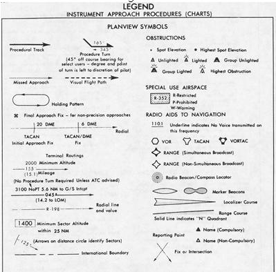
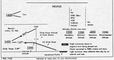
f. Legend Pages contain the Plain View Symbols, Profile information, Aerodrome Sketch information, and General Information and Abbreviations. The following figures 3 and 4 are Legend Pages to the Coast and Geodetic Survey instrument approach procedures charts.
Figure 3.
|
|
|
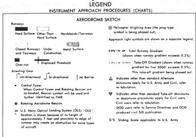
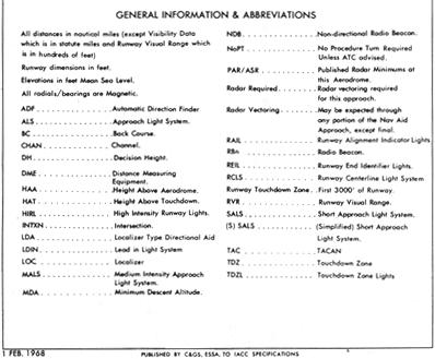
Figure 4.
 |
|
 |
g. Revised Format For Government-Produced Instrument Approach
Procedure Charts.
Complete revision to instrument approach chart format has been
made. Each chart consists of five sections: margin identification, plan
view, profile view, landing minimum section (and notes), and aerodrome
sketch. See figures 5 and 6 below.
Figure 5.
 |
|
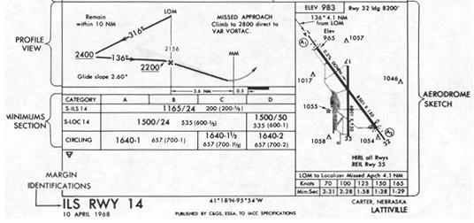 |
Figure 6.
 |
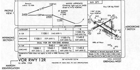 |
Figure 7.
 |
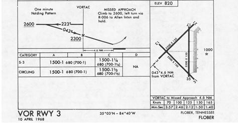 |
Figure 8.
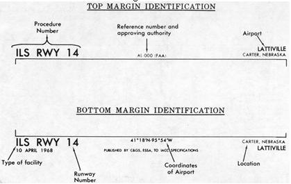 |
(1) Margin Identification.
(a) The procedure identification is derived from the type
facility providing final approach course guidance and (1) runway number
when the approach course is within 30° of the runway centerline, i.e.,
ILS Rwy 14, or (2) sequential number for the airport when the approach
course is more than 30° from runway centerline, i.e., VOR-1, VOR-2,
etc.
(b) Nondirectional Beacon (NDB), Localizer (LOC) and Localizer
Type Directional Aid (LDA) are used to identify more accurately the type
facility providing final approach course guidance.
1 "NDB" procedure number replaces ADF type procedure.
2 "LOC" procedure number indicates that a localizer
provides course guidance and a glide slope (ground facility) has not been
installed. (Includes ILS back course procedures.)
3 "LDA" procedure number is the same as localizer
but is not aligned with the runway centerline. The approach chart should
be examined to determine the direction and degrees of alignment away from
runway centerline.
(c) VOR/DME procedure number means that both operative
VOR and DME receivers and ground equipment in normal operation are required
to use the procedure. As stated previously, in the VOR/DME procedure, when
either the VOR or DME is inoperative, the procedure is not authorized.
(d) When DME arcs and DME fixes are authorized in a procedure
and the procedure number does not include the three letter "DME" type of
facility in the margin identification, the procedure may be used without
utilizing the DME equipment.
(e) VORTAC type procedure is a VOR/DME procedure that
is authorized for an aircraft equipped with either VOR/DME or TACAN receiver.
Figure 9.
 |
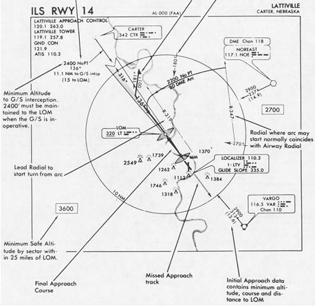 |
Figure 10.
 |
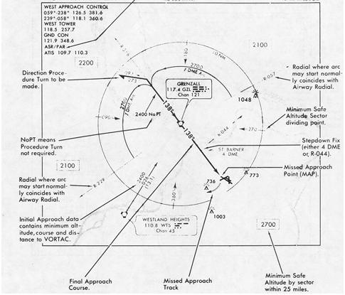 |
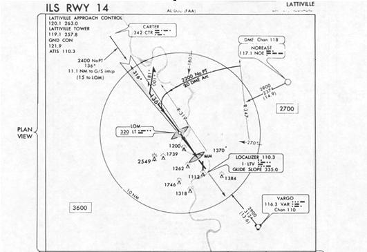
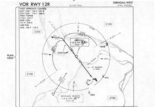
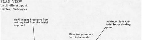
(2) Plan View (Figures 7, 9, and 10). This is a bird's eye view
of the entire procedure. Information pertaining to the initial approach
segment, including procedure turn, minimum safe altitude for each sector,
courses prescribed for the final approach segment and obstructions, is
portrayed in this section. Navigation and communication frequencies are
also listed on the plan view.
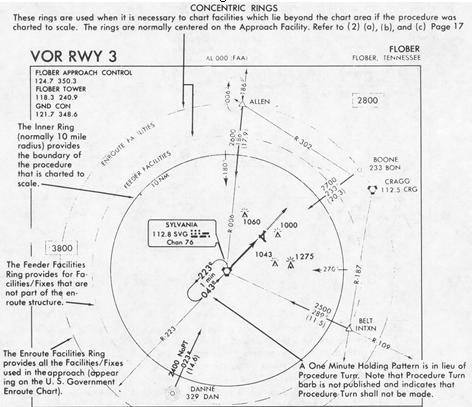
(a) Format. Normally, all information within the plan
view is shown to scale. Data shown within the 10 NM distance circle is
always shown to scale. (See figure 7.) The dashed circles, called concentric
rings, are used when all information necessary to the procedure will not
fit to scale within the limits of the plan view area. These circles then
serve as a means to systematically arrange this information in their relative
position outside and beyond the 10 NM distance circle. These concentric
rings are labeled Enroute Facilities and Feeder Facilities.
(b) Enroute Facilities Ring. (See figure 7.) Radio aids
to navigation, fixes and intersections that are part of the Enroute Low
Altitude Airway structure and used in the approach procedure are shown
in their relative position on this Enroute Facilities Ring.
(c) Feeder Facilities Ring. (See figure 7.) Radio aids
to navigation, fixes and intersections used by the air traffic controller
to direct aircraft to intervening facilities/fixes between the enroute
structure and the initial approach fix are shown in their relative position
on this Feeder Facilities Ring.
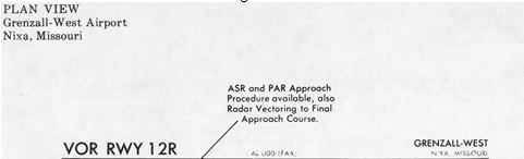
(d) The Availability of Radar (see figure 10) is indicated
below the communications information by the appropriate and applicable
letters "ASR", "PAR", "ASR/PAR" or "RADAR VECTORING." These terms are applied
as follows:
1 ASR - means Airport Surveillance Radar instrument
approach procedures are available at the airport, and also that Radar Vectoring
is available for the procedure.
2 PAR - means Precision Approach Radar instrument
approach procedures are available.
3 Radar Vectoring - means Radar Vectoring is available
but radar instrument approach procedures are not available.
(e) The Term "Initial Approach" is explained in section
97.3(c)(1) of Part 97 of the Federal Aviation Regulations. It is further
explained in the FAA Handbook "U.S. Standard for Terminal Instrument Procedures
(TERPs)", page 15 section 3, Initial Approach.
1 In the initial approach, the aircraft has departed
the enroute phase of flight, and is maneuvering to enter an intermediate
or final segment of the instrument approach.
2 An initial approach may be made along prescribed
routes within the terminal area which may be along an arc, radial, course,
heading, radar vector, or a combination thereof. Procedure turns and high
altitude teardrop penetrations are initial approach segments.
3 Initial approach information is portrayed in the
plan view of the instrument approach charts by course lines, with an arrow
indicating the direction. Minimum altitude and distance between fixes is
also shown with the magnetic course.
4 When the term "NoPT" appears, an intermediate
approach is provided. These altitudes shown with the term "NoPT" cannot
be used as an initial approach altitude for the purpose of determining
alternate airports requirements under FAR 91.23(c) {§ 91.23 recodified
to § 91.167} and 91.83(b) {§ 91.83 recodified to § 91.153}.
(f) When an approach course is published on an ILS procedure
that does not require a procedure turn (NoPT), the following applies.
1 In the case of a dog-leg track and no fix is depicted
at the point of interception on the localizer course, the total distance
is shown from the facility or fix to the LOM, or to an NDB associated with
the ILS.
2 The minimum altitude applies until the glide slope
is intercepted, at which point the aircraft descends on the glide slope.
3 When the glide slope is not utilized, this minimum
altitude is maintained to the LOM (or to the NDB if appropriate).
4 In isolated instances, when proceeding NoPT to
the LOM and the glide slope cannot be utilized, a procedure turn will be
required to descend for a straight-in approach and landing. In these cases,
the requirement for a procedure turn will be annotated on the Plan View
of the procedure chart.
(g) Procedure turn is the maneuver prescribed when it is necessary to reverse direction to establish the aircraft inbound on an intermediate or final approach course. It is a required maneuver except when the symbol NoPT is shown, when radar vectoring is provided, when a one minute holding pattern is published in lieu of a procedure turn, or when the procedure turn is not authorized. The altitude prescribed for the procedure turn is a MINIMUM altitude until the aircraft is established on the inbound course. The maneuver must be completed within the distance specified in the profile view.
1 A barb indicates the direction or side of the outbound
course on which the procedure turn is made. Headings are provided for course
reversal using the 45° type procedure turn. However, the point at which
the turn may be commenced and the type and rate of turn is left to the
discretion of the pilot. Some of the options are the 45° procedure
turn, the racetrack pattern, the tear-drop procedure turn, or the 80°
- 260° course reversal. These maneuvers are diagrammed in the FAA Instrument
Flying Handbook (AC 61-27A), and the steps numbered under the figures are
intended for student practice under no-wind conditions.
2 Limitations on procedure turns.
a In the case of a radar initial approach
to a final approach fix or position, or a timed approach from a holding
fix, or where the procedure specifies "NoPT", no pilot may make a procedure
turn unless, when he receives his final approach clearance, he also advises
ATC and a clearance is received.
b When a tear-drop procedure turn is depicted
and a course reversal is required, this type turn must be executed.
c When a one minute holding pattern replaces
the procedure turn, the standard entry and the holding pattern must be
followed except when RADAR VECTORING is provided or when NoPT is shown
on the approach course. Diagrams of the holding pattern and entries into
the pattern also are illustrated in the Handbook 61-27A. As in the procedure
turn, the descent from the minimum holding pattern altitude to the final
approach fix altitude (when lower) may not commence until the aircraft
is established on the inbound course.
d The absence of the procedure turn barb in
the Plan View indicates that a procedure turn is not authorized for that
procedure.
3 A Procedure Turn is not required when the symbol
NoPT appears on an approach course shown on the Plan View. If a procedure
turn is desired, descent below the procedure turn altitude should not be
made since some NoPT altitudes may be lower than the procedure turn altitude.
Figure 11.
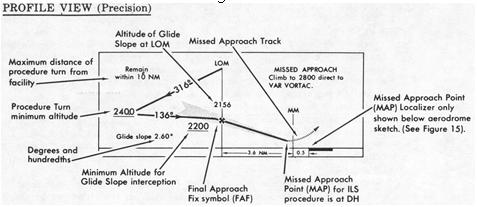 |
Figure 12.
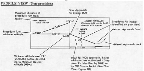 |
(3) Profile views (Figures 11 and 12) show a side view of the
procedures. These views include the minimum altitude and maximum distance
for the procedure turn, altitudes over prescribed fixes, distances between
fixes and the missed approach procedure.
(a) Precision approach glide slope intercept altitude.
This is a minimum altitude for glide slope interception after completion
of procedure turn. It applies to precision approaches and, except where
otherwise prescribed, it also applies as a minimum altitude for crossing
the final approach fix in case the glide slope is inoperative or not used.
(b) Stepdown fixes in non-precision procedures. A stepdown
fix may be provided on the final, i.e., between the final approach fix
and the airport for the purpose of authorizing a lower MDA after passing
an obstruction. This stepdown fix may be made by an NDB bearing, fan marker,
radar fix, radial from another VOR, or by a DME when provided for as shown
in figure 12.
(c) Normally, there is only one stepdown fix between the
final approach fix (FAF) and the missed approach point (MAP). If the stepdown
fix cannot be identified for any reason, the altitude at the stepdown fix
becomes the MDA for a straight-in landing. However, when circling under
this condition, you must refer to the Minimums Section of the procedure
for the applicable circling minimum. See figure 14 for example.
(d) Missed approach point (MAP). It should be specifically
noted that the missed approach points are different for the complete ILS
(with glide slope) and for the localizer only approach. The MAP for the
ILS is at the decision height (DH) while the "localizer only" MAP is usually
over the (straight-in) runway threshold. In some non-precision procedures,
the MAP may be prior to reaching the runway threshold in order to clear
obstructions in the missed approach climb-out area. In non-precision procedures,
the pilot determines when he is at the missed approach point (MAP) by timing
from the final approach fix (FAF). The FAF has been clearly identified
by use of the maltese cross symbol in the profile section. The distance
from FAF to MAP and time and speed table, for easy calculation, are found
below the aerodrome sketches (figures 15 and 16). This does not apply to
VOR/DME procedures, or when the facility is on the airport and the facility
is the MAP.
Figure 13.
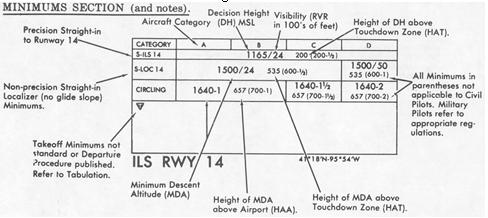 |
Figure 14.
 |
(4) Minimum section.
(a) The same minimums apply to both day and night operations
unless different minimums are specified at the bottom of the minimum box
in the space provided for symbols or notes.
(b) The minimums for straight-in and circling appear directly
under each aircraft category. When there is no division line between minimums
for each category on the straight-in or circling lines, the minimums apply
to two or more categories under the A, B, C, or D.
(For figure 13, the S-ILS 14 minimums apply to all four
categories. The S-localizer 14 minimums are the same for Categories A,
B, and C, and different for Category D. The circling minimums are the same
for A and B and individually different for C and D.)
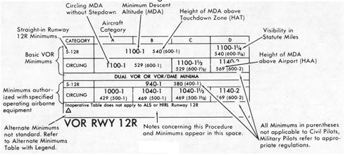
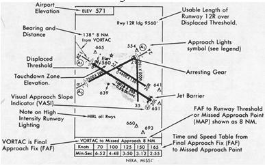
(c) The Nixa, Missouri, Grenzall West Airport, VOR Rwy
12R procedure (figures 12 and 14) authorizes minimums for aircraft with
one VOR receiver. Lower minimums are authorized if the aircraft also has
DME or dual VOR receivers and St. Barner Intersection is identified. (See
figure 14 for dual minimums.)
(5) Aerodrome data.
Figure 15.
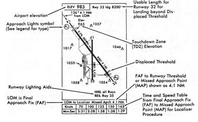 |
Figure 16.
 |
(6) General information.
(a) During pre-flight planning prior to departure on an
IFR flight plan, reference should be made to instrument approach charts
to determine:
1 Take-off minimums.
2 Whether an IFR departure procedure for obstruction
avoidance has been established.
Instrument approach charts in the old format have
take-off minimums and departure procedures published on the chart. Procedures
published under the revised format do not contain this information. Take-off
minimums are standard (see paragraph 3.b.) unless the symbol is shown
under the minimums box indicating that the separate listing should be consulted.
Below is an example of this listing.
Figure 17.
INSTRUMENT APPROACH PROCEDURES (CHARTS)
SOUTHEAST UNITED STATES
IFR TAKE-OFF MINIMUMS AND DEPARTURE PROCEDURES
FAR 91.116(c) {§ 91.116 recodified to § 91.175} prescribes
take-off rules for FAR 121, 129, and 135 operators and establishes standard
take-off visibility minimums as follows:
(1) Aircraft having two engines or less - one statue mile.
(2) Aircraft having more than two engines - one-half statute mile.
Aerodromes within this geographical area with IFR take-off minimums
other than standard are listed below alphabetically be aerodrome name.
Departure procedures and/or ceiling and visibility minimums are established
to assist pilots conducting IFR flight in avoiding obstructions during
climb to the minimum enroute altitude.
Take-off minimums and departure procedures apply to all runways unless
otherwise specified.
AERODROME NAME TAKE-OFF MINIMUM AERODROME NAME TAKE-OFF MINIMUMS
CARTER-LATTIVILLE 500-2
Carter, Nebraska
(b) When use of an alternate airport is required in filing an IFR flight plan (FAR 91.83 {§ 91.83 recodified to § 91.153}), reference should be made to the instrument approach procedure to be used for the alternate selected to determine alternate airport minimums. Procedures charted in the old format have alternate minimums shown on the chart. Procedures charted in the new format do not contain this information. Alternate minimums are standard (see paragraph 3.c.) unless the symbol is shown under the minimums box indicating that alternate minimums are not standard and that the separate listing should be consulted. If the airport is not authorized for use as an alternate, the letters "NA" will follow the symbol under the minimum box. Below is an example of the Alternate Minimums listing.
Note: If the pilot elects to proceed to the selected alternate airport, the alternate ceiling and visibility minimums are disregarded, and the published landing minimum is applicable for the new destination utilizing facilities as appropriate to the procedure. In other words, the alternate airport becomes a new destination, and the pilot uses the landing minimum appropriate to the type of procedure selected.
Figure 18.
INSTRUMENT APPROACH PROCEDURES (CHARTS)
WEST CENTRAL UNITED STATES
IFR ALTERNATE MINIMUMS
(Not applicable to USAF/USN)
Standard alternate minimums for nonprecision approaches are 800-2 (NDB,
VOR, LOC, TACAN, LDA, VORTAC, VOR/DME or ASR); for precision approaches
600-2 (ILS or PAR). Aerodromes within this geographical area that require
alternate minimums other than standard or alternate minimum with restrictions,
are listed below. U.S. Army pilots refer to Army Reg. 95-2 for additional
application. Civil pilots see FAR 91.83 {§ 91.83 recodified to §
91.153}. USAF/USN pilots refer to appropriate regulations.
AERODROME NAME ALTERNATE MINIMUMS AERODROME NAME ALTERNATE MINIMUMS
NIXA GRENZALL ARPT VOR Rwy 12R
Nixa, Missouri
Categories A, B and C, 1100-2;
category D, 1200-2
(c) The tables which appear as samples in (a) and (b) above
are printed for area chart books, and should be kept with the Legend pages
and Inoperative Components or Visual Aids Table at the front of each area
chart book.
(d) Straight-in minimums are shown on instrument approach
procedure charts when the final approach course of the instrument approach
procedure is within 30° of the runway alignment and a normal descent
can be made from the IFR altitude shown on the instrument approach procedures
to the runway surface. When either the normal rate of descent or the runway
alignment factor of 30° is exceeded, a straight-in minimum is not published
and a circling minimum applies. The fact that a straight-in minimum is
not published does not preclude the pilot from landing straight-in if he
has the active runway in sight in sufficient time to make a normal landing.
Under such conditions and when Air Traffic Control has cleared him for
landing on that runway, he is not expected to circle even though only circling
minimums are published. If he desires to circle at a controlled Airport,
he should advise ATC.
(e) Circling minimums. The circling minimums published
on the instrument approach chart provide adequate obstruction clearance
and the pilot should not descend below the circling altitude until the
aircraft is in a position to make final descent for landing. Sound judgement
and knowledge of his and the aircraft capabilities are the criteria for
a pilot to determine the exact maneuver in each instance since the airport
design, the aircraft position, altitude and airspeed must all be considered.
The following basic rules apply.
1 Maneuver the shortest path to the base or downwind
leg as appropriate under minimum weather conditions. There is no restriction
from passing over the airport or other runways.
2 It should be recognized that many circling maneuvers
may be made while VFR flying is in progress at the airport. Standard left
turns or specific instruction from the controller for maneuvering must
be considered when circling to land.
3 At airports without a control tower, it may be
desirable to fly over the airport to determine wind and turn indicators,
and to observe other traffic which may be on the runway or flying in the
vicinity of the airport.
(f) When the missed approach procedure specifies holding
at a facility or fix, holding shall be in accordance with the holding pattern
depicted on the plan view, and at the minimum altitude in the missed approach
instructions, unless a higher altitude is specified by ATC. An alternate
missed approach procedure may also be given by ATC.
(g) There are various terms in the missed approach procedure
which have specific meanings with respect to climbing to altitude, to execute
a turn for obstruction avoidance, or for other reasons. Examples:
`Climb to' means a normal climb along the prescribed
course.
`Climbing right turn' means climbing right turn
as soon as safety permits, normally to avoid obstructions straight ahead.
`Climb to 2400 turn right' means climb to 2400 prior
to making the right turn, normally to clear obstructions.