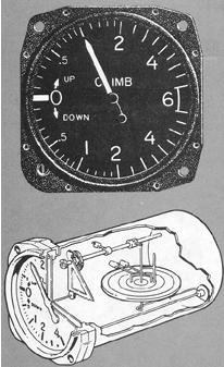
The vertical-speed indicator (also called the vertical-velocity or rate-of-climb indicator) is contained within a sealed case, connected to the static pressure line through a calibrated leak. As shown in Figure 4-12, changing pressures expand or contract a diaphragm, connected to the indicating needle through gears and levers. The instrument automatically compensates for changes in temperature.
Figure 4-12. Vertical-speed indicator components.
|
Although the vertical-speed indicator operates from the static pressure source, it is a differential pressure instrument. The differential pressure is established between the instantaneous static pressure in the diaphragm and the trapped static pressure within the case.
When the pressures are equalized in level flight, the needle reads zero. As static pressure in the diaphragm changes during entry to a climb or descent, the needle immediately shows a change of vertical direction. However, until the differential pressure stabilizes at a definite ratio, reliable rate indications cannot be read. Because of the restriction in air flow through the calibrated leak, a 6- to 9-second lag is required to equalize or stabilize the pressures.
Limitations in the use of the vertical-speed indicator are due to the calibrated leak. Sudden or abrupt changes in aircraft attitude cause erroneous instrument readings as the air flow fluctuates over the static ports. Both rough control technique and turbulent air result in unreliable needle indications. When used properly, the instrument provides reliable information to establish and maintain level flight and rate climbs or descents.
The instantaneous vertical-speed indicator incorporates acceleration pumps to eliminate the limitations associated with the calibrated leak. For example, during climb entry, vertical acceleration causes the pumps to supply extra air into the diaphragm to stabilize the pressure differential without the usual lag time. During the level flight and steady rate climbs and descents, the instrument operates on the same principles as the earlier conventional type.
Adjustment. The needle of the vertical velocity indicator should indicate zero when the aircraft is on the ground or maintaining a constant pressure level in-flight. Most instruments can be adjusted to a zero reading by turning a screw on the lower left corner of the instrument case. If this adjustment cannot be made, you must allow for the error when interpreting the indications in flight.
Airspeed Indicator
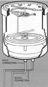
The airspeed indicator is constructed to measure the difference between ram pressure from the pitot head and atmospheric pressure from the static source. The instrument (Fig. 4-13) is contained within a sealed case in which is mounted a diaphragm sensitive to pressure changes. The impact pressure line is connected directly to one side of the diaphragm, while the inside of the case is vented to the static source. As the aircraft accelerates or decelerates, expansion or contraction of one side of the diaphragm moves the indicator needle by means of gears and levers. The airspeed dial may show indicated airspeed, true airspeed, Mach (airspeed converted to a decimal fraction of the speed of sound), or a combination of these values calibrated in miles per hour or knots.
Airspeed Errors. Airspeed, like altitude, is a general term that must be more specifically identified for its application to flying. The instrument is designed to provide speed information under specific limited conditions. Whenever the conditions alter, errors are introduced.
Position error is caused by the static ports sensing erroneous static pressure. The slipstream flow causes disturbances at the static ports preventing actual atmospheric measurement. The error varies with airspeed, altitude, and configuration and may be a plus or a minus value. The error may be determined by reference to an airspeed calibration chart or table. The chart or table may be posted near the airspeed indicator, or included in the Airplane Flight Manual or owner's handbook.
Density error is introduced by changes in altitude and temperature
for which the instrument does not automatically compensate. The standard
airspeed instrument cannot adjust for variations from sea level standard
atmosphere conditions.
Compressibility error is caused by the packing of air into the
pitot tube at high airspeeds, resulting in higher than normal readings.
Below approximately 180 knots and at low altitudes the error is negligible.
Figure 4-13. Airspeed indicator components.
 |
Types of Airspeed
Indicated airspeed is the value read on the face of a standard airspeed indicator. The indicator is calibrated to reflect standard atmosphere adiabatic compressible flow at sea level corrected for airspeed system errors. It can be read in miles per hour or in knots, depending upon the scale of the dial.
Calibrated airspeed is the indicated airspeed of an aircraft, corrected for position and instrument error. Calibrated airspeed is equal to true airspeed in standard atmosphere at sea level.
Equivalent airspeed is the calibrated airspeed of an aircraft corrected for adiabatic compressible flow for the particular altitude. Equivalent airspeed is equal to calibrated airspeed in standard atmosphere at sea level; it is significant to pilots of high speed aircraft, but relatively unimportant to the average light plane pilot.
True airspeed is the airspeed of an aircraft relative to undisturbed
air. It is equivalent airspeed corrected for air-density variation from
the standard value at sea level. True airspeed increases with altitude
when indicated airspeed remains the same.
Mach number is the ratio of true airspeed to the speed of sound.
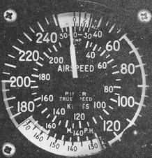
True Airspeed Indicator
The true airspeed indicator combines computer operation and indicator in one instrument to provide both true and indicated airspeed (within the cruising speed range).
Figure 4-14 illustrates the current trend in the design of flight instruments which reduce pilot workload. With the adjusting knob, pressure altitude is set opposite outside air temperature. The needle then shows indicated airspeed in both knots and miles per hour, and true airspeed in m.p.h. More advanced true airspeed indicators contain diaphragms which respond to barometric pressure, free air temperature, and impact pressure. These factors are mechanically resolved to provide true airspeed indications.
Figure 4-14. True airspeed indicator.
 |
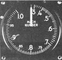
Mach Indicator
The Mach indicator (Fig. 4-15) is found on more recently developed high performance aircraft. It indicates the ratio of aircraft true airspeed to the speed of sound at flight altitude. The Mach pointer is actuated mechanically by the pressure differential between impact air and static air pressure. In computing a true airspeed from indicated airspeed, air density must be taken into account. This requires a correction for temperature and altitude. With a Mach number, these corrections are unnecessary because the existing temperature at flight level determines the speed of sound at flight level. The Mach number is determined by the speed of sound, which in turn is determined by air density; thus, Mach is always a valid index to the speed of the aircraft.
Figure 4-15. Mach indicator.
 |
Gyroscopic Instruments
Of the six basic flight instruments, three (attitude indicator, turn indicator, and heading indicator) are controlled by gyroscopes. Understanding the use of these instruments requires a knowledge of gyroscopic principles, instrument power systems, and the construction and operating details of each instrument. Without the gyroscope and its practical adaptation to flight and navigational instruments, precision all-weather flying would be impossible.
Gyroscopes. Any rotating body exhibits gyroscopic properties according to Newton's laws of motion. The first law states: A body at rest will remain at rest; or if in motion in a straight line, it will continue in motion in a straight line unless acted upon by an outside force. The second law states: The deflection of a moving body is proportional to the deflective force applied and is inversely proportional to its weight and speed. A gyroscope, or gyro, is a wheel or disc designed to utilize these principles.
Gyroscopic inertia depends upon several design factors:
1. Weight. For a given size, a heavier mass is more resistant
to disturbing forces than a lighter mass.
2. Angular Velocity. The higher the rotational speed, the greater
the rigidity, or resistance to deflection.
3. Radius at Which the Weight Is Concentrated. Maximum effect
is obtained from a mass when its principal weight is concentrated near
the rim rotating at high speed.
4. Bearing Friction. Any friction applies a deflecting force
to a gyro. Minimum bearing friction keeps deflecting forces at a minimum.
Two types of mounting are used, depending upon how the gyroscopic properties are to be used in the operation of the instrument. A freely or universally mounted gyro is set on three gimbals, with the gyro free to rotate in any plane. Regardless of the position of the gyro base, the gyro tends to remain rigid in space. In the attitude indicator, the horizon bar is gyro-controlled to remain parallel to the natural horizon, and changes in position of the aircraft are shown pictorially (Fig. 4-17).
The semirigid, or restricted, mounting employs two gimbals, limiting
the rotor to two planes of rotation. In the turn indicator, the semirigid
mounting is used to provide controlled precession of the rotor, and the
precessing force exerted on the gyro by the turning aircraft causes the
needle to indicate a turn (Fig. 4-18).