A gyroscope is a spinning mass or wheel, universally mounted, so that only one point - its center of gravity - is in a fixed position, the wheel being free to turn in any direction around this point. To simplify this explanation we will illustrate the construction of a demonstrating model step by step.
Figure 4-16. Principles of the gyroscope.
1. Picture a rotor and axle, with the rim of the rotor more or less facing you.
2. Give it a supporting ring, with bearings on which the rotor and its axle can revolve.
 |
3. Now add an outer ring with bearings at 90° to the rotor bearings, about which the inner ring with its rotor and axle can turn.
 |
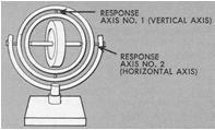
4. Draw a frame which will support the rotor and its rings on horizontal bearings; this will complete your demonstrating model gyroscope. Disregarding the spin axis, the gyroscope has two degrees of freedom; the assembly can turn about a vertical axis (response axis No. 1) and also about a horizontal axis (response axis No. 2).
 |
5. When at rest there's nothing unusual about a gyroscope. It's simply a wheel universally mounted. You can point its axle in any direction without altering the geometrical center of the assembly.
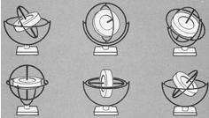 |
6. But when you spin the rotor the gyroscope exhibits the first of its two characteristics. It acquires a high degree of rigidity and its axle keeps pointing in the same direction no matter haw much you turn the base about. This is gyroscopic inertia.
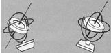 |
7. The second characteristic, precession, may be illustrated by applying a force or pressure to the gyro about the horizontal axis as shown below (1). It will be found that the applied pressure meets with resistance and that the gyro, instead of turning about its horizontal axis, turns or "precesses" about its vertical axis in the direction indicated by the arrow P. Similarly, if we apply a pressure about the vertical axis, the gyro will precess about its horizontal axis as shown by the arrow P at right, below (2).
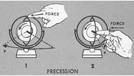 |
Figure 4-17. Attitude indicator or gyro-horizon.
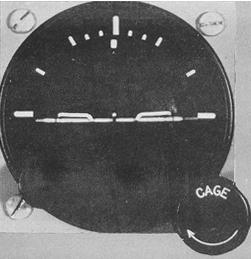 |
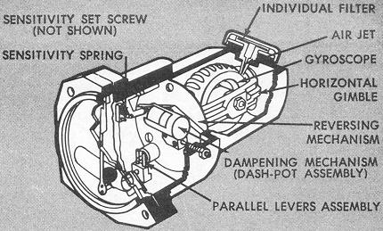
Figure 4-18. Turn indicator.
 |
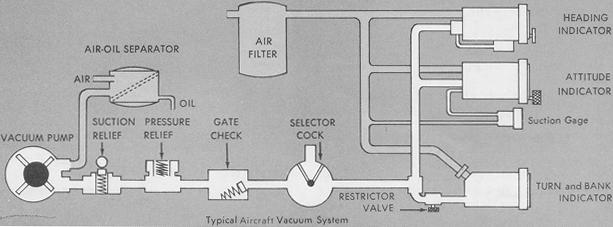
Engine-Driven Vacuum Pumps. The vane-type engine-driven pump is the most common source of vacuum for gyros installed in general aviation light aircraft. One type of engine-driven pump is mounted on the accessory drive shaft of the engine, and is connected to the engine lubrication system to seal, cool, and lubricate the pump. The diagram in Figure 4-19 shows the components of a vacuum system with a pump capacity of approximately 10" Hg at engine speeds above 1000 rpm. Pump capacity and pump size vary in different aircraft, depending on the number of gyros to be operated.
Air-Oil Separator. Oil and air in the vacuum pump is exhausted through the separator, which separates the oil from the air, vents the air outboard, and returns the oil to the engine sump.
Suction Relief Valve. Since the system capacity is more than is needed for operation of the instruments, the adjustable suction relief valve is set for the vacuum desired for the instruments. Excess suction in the instrument lines is reduced when the spring-loaded valve opens to atmospheric pressure.
Figure 4-19. Pump-driven vacuum system.
 |
Pressure Relief Valve. Since a reverse flow of air from the pump
would close both the gate check valve and the suction relief valve, the
resulting pressure could rupture the lines. The pressure relief valve vents
positive pressure into the atmosphere.
Gate Check Valve. The gate check valve prevents possible damage
to the instruments by engine backfire, which would reverse the flow of
air and oil from the pump.
Selector Cock. In twin-engine aircraft having vacuum pumps driven
by both engines, the alternate pump can be selected to provide vacuum in
the event of either engine or pump failure, with a check valve incorporated
to seal off the failed pump.
Restrictor Valve. Since the turn needle operates on less vacuum
than that required for other gyro instruments, the vacuum in the main line
must be reduced. This valve is either a needle valve adjusted to reduce
the vacuum from the main line by approximately one-half, or a spring-loaded
regulating valve that maintains a constant vacuum for the turn indicator,
unless the main line vacuum falls below a minimum value.
Air Filter. The master air filter screens foreign matter from the air flowing through all the gyro instruments, which are also provided with individual filters. Clogging of the master filter will reduce airflow and cause a lower reading on the suction gage. In aircraft having no master filter installed, each instrument has its own filter. With an individual filter system, clogging of a filter will not necessarily show on the suction gauge.
Suction gauge. The suction gauge is a pressure gauge, indicating
the difference, in inches of mercury, between the pressure inside the system
and atmospheric or cockpit pressure. The desired vacuum, and the minimum
and maximum limits, vary with gyro design. If the desired vacuum for the
attitude and heading indicators is 5" and the minimum is 4.6", a reading
below the latter value indicates that the airflow is not spinning the gyros
fast enough for reliable operation. In many aircraft, the system provides
a suction gauge selector valve, permitting the pilot to check the vacuum
at several points in the system.
Another commonly used source of vacuum is the dry vacuum pump,
also engine-driven. The pump operates without lubrication, and the installation
requires no lines to the engine oil supply, and no oil separator or gate
check valve. In other respects, the dry pump system and oil lubricated
system are the same.
The principal disadvantage of the pump-driven vacuum system relates to erratic operation in high altitude flying. Apart from routine maintenance of the filters and plumbing, which are absent in the electric gyro, the engine-driven pump is as effective a source of power for light aircraft as the electrical system.
Electrical System. The electrically driven gyro was designed for military aircraft instruments after tests showed erratic operation of vacuum-driven gyros at high altitude. At 18,000 feet, in atmospheric pressure approximately half of that at sea level, the vacuum pump is about half as efficient as at sea level. At progressively higher altitudes or extremely low temperatures affecting oil viscosity, the vacuum system will not create enough suction to operate the gyros at desired speed.
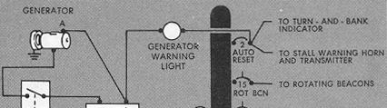
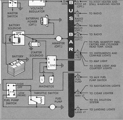
The principal value of the electric gyro in light aircraft is its safety factor. In single-engine aircraft equipped with vacuum-driven attitude and heading indicators, the turn needle is commonly operated by an electric gyro. In the event of vacuum system failure and loss of two gyro instruments, the pilot still has a reliable standby instrument for emergency operation. Operated on current directly from the battery, the electric turn indicator is reliable as long as current is available, regardless of generator or vacuum system malfunction. In the electric instrument, the gyro is a small electric motor and flywheel. Otherwise, both electric and vacuum-driven turn-needles are designed to use the same gyroscopic principle of recession. Figure 4-20 shows a typical 12-volt direct-current light plane electrical system.
Figure 4-20. Electrical system
 |
|
 |
Attitude Indicators
The attitude indicator - also referred to as the gyro-horizon,
attitude gyro, and artificial horizon - is constructed to show the attitude
of your aircraft in relation to the natural horizon when for any reason
you must, or choose to, control your aircraft by visual reference inside,
rather than outside, the cockpit. Irrespective of variations in instrument
design, all attitude indicators relate a gyro-controlled artificial horizon
line to some form of pitch and bank reference.