The value of the attitude indicator is directly related to the readability of the instrument; that is, to the speed and ease with which you can get information from it to determine exact aircraft attitude.
Although the older type attitude indicators are not difficult to interpret in normal flight attitudes, reference to other instruments to confirm the indications observed on the attitude indicator is recommended and particularly when abnormal flight attitudes are experienced. The greater the divergence of the miniature aircraft from the horizon line, the more difficult exact interpretation becomes, yet the extreme attitude is the condition requiring immediate and accurate visual information.
The operation of the bank index can also be confusing. When the aircraft is banked to the right, the index moves left (counterclockwise) and vice versa. Students commonly misinterpret this motion of the bank index and apply aileron control in the wrong direction. Requirements of high performance aircraft have accelerated research to improve readability and reliability of the attitude gyro.
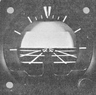
One improved attitude indicator design is shown in Figure 4-27. In this design, the "SLOTTED" bank index has been moved to the upper periphery of the case to improve readability of the angle of bank as read on the graduated scale which is attached to the case. Further bank references are to be seen in the form of converging lines to a point on the horizon. Pitch references are the horizon line and the ground lines parallel to the horizon line.
Figure 4-27. Simplified attitude indicator design.
|
Several of the attitude indicators being installed in recently manufactured general aviation aircraft are non-tumbling, self-erecting, and have turn errors compensated. They may be either electric or vacuum driven instruments.
Turn and Slip Indicator
The turn and slip indicator, also referred to as the "needle and ball" and "turn and bank" indicator, was the only available reference for bank attitude before the development of the attitude indicator. Its principal uses in modern aircraft are to indicate trim and to serve as an emergency source of bank information in case the attitude gyro fails.
The turn and slip indicator is actually a combination of two instruments. The needle is gyro-operated to show rate of turn and the ball reacts to gravity and/or centrifugal force to indicate the need for directional trim.
Turn Needle Operation.
The turn needle is operated by a gyro, driven either by vacuum or electricity. Semirigid mounting of the gyro permits it to rotate freely about the lateral and longitudinal axes while restricting its rotation about the vertical axis. The gyro axis is horizontally mounted so that the gyro rotates up and away from the pilot. The gimbal around the gyro is pivoted fore and aft.
Gyroscopic precession causes the rotor to tilt when the aircraft is turned. Due to the direction of rotation, the gyro assembly tilts in the opposite direction from which the aircraft is turning; this prevents the rotor axis from becoming vertical to the earth's surface. The linkage between the gyro assembly and the turn needle, called the reversing mechanism, causes the needle to indicate the proper direction of turn.
A spring is attached between the instrument case and the gyro assembly to hold the gyro upright when no precession force is applied. Tension on the spring may be adjusted to calibrate the instrument for a given rate of turn. The spring restricts the amount of gyro tilt. Stops prevent the gyro assembly from tilting more than 45° to either side of the upright position. In addition, a damping mechanism prevents excessive oscillation of the turn needle.
Power for the electric gyro may be supplied from either an AC
or DC source. When current is supplied directly from the battery, the needle
gives reliable indications regardless of malfunction or failure of other
components of the electrical system.
Power for the suction-driven turn needle is regulated by a restrictor
valve installed between the main suction line and the instrument to produce
a desired suction and rotor speed. Since the needle measures the force
of precession, excessively high or low vacuum results in unreliable turn
needle operation. For a specific rate of turn, low vacuum produces less
than normal rotor speed and, therefore, less precession force. Needle deflection
is, therefore, less for this specific rate of turn. The reverse is true
for the condition of high vacuum.
The turn needle indicates the rate at which the aircraft is turning about the vertical axis in number of degrees per second. Properly understood, the instrument provides bank as well as rate-of-turn information but it tells you nothing about bank attitude unless you understand the relationship between airspeed, angle of bank, and rate of turn discussed in Chapter III, "Aerodynamic Factors Related to Instrument Flying."
Of the two types of turn needle shown in Figure 4-28, the 2-minute turn indicator is the older. If the instrument is accurately calibrated, a single needle-width deflection on the 2-minute indicator means that the aircraft is turning at 3° per second, or standard rate (2 minutes for a 360° turn). On the 4-minute indicator, a single needle-width deflection shows when the aircraft is turning at 1-1/2° per second, or half standard rate (4 minutes for a 360° turn). From a comparison of the indexes on the two instruments, you can see why the 4-minute instrument was developed: The half standard-rate (one-needle width deflection) turn used by high-speed aircraft is more easily read on the 4-minute indicator.
Slip Indicator (Ball) Operation.
This part of the instrument is a simple inclinometer consisting of a sealed, curved glass tube containing kerosene and a black agate or common steel ball bearing which is free to move inside the tube. The fluid provides a dampening action, insuring smooth and easy movement of the ball. The tube is curved so that in a horizontal position the ball tends to seek the lowest point. A small projection on the left end of the tube contains a bubble of air which compensates for expansion of the fluid during changes in temperature. Two strands of wire wound around the glass tube fasten the tube to the instrument case and also serve as reference markers to indicate the correct position of the ball in the tube. During coordinated straight-and-level flight, the force of gravity causes the ball to rest in the lowest part of the tube, centered between the reference wires.
Figure 4-28. Turn indicators (2- and 4-minute)
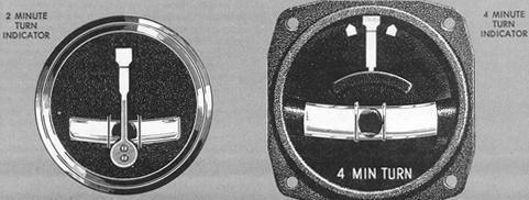 |
Figure 4-29 shows the forces acting on the ball during turns. During a coordinated turn these forces are in balance, allowing the ball to remain in the center of the tube. When the forces acting on the ball become unbalanced, the ball moves away from the center of the tube.
In a skid, the rate of turn is too great for the angle of bank, and excessive centrifugal force causes the ball to move to the outside of the turn. To correct to coordinated flight calls for increasing the bank or decreasing the rate of turn or a combination of both.
In a slip, the rate of turn is too slow for the angle of bank, and the lack of centrifugal force causes the ball to move to the inside of the turn. To return to coordinated flight requires decreasing the bank or increasing the rate of turn, or a combination of both. The ball is thus used to check for coordinated flight. It is actually a "balance" indicator since it shows the relationship between the angle of bank and the rate of turn. Note that in each instance shown in Figure 4-29 the aircraft is turning at half standard rate, regardless of the position of the ball.
Errors.
Errors in turn needle indications are due to (1) insufficient
or excessive rotor speed; or (2) inaccurate adjustment of the calibrating
spring.
Turn Coordinator
Recent years have seen the development of a new type of turn indicator,
referred to as a "Turn Coordinator" or "Pictorial Turn Indicator." In place
of the conventional turn needle indication of rate-of-turn, both instruments
pictured in Figure 4-30, display a movement of the aircraft on the roll
axis that is proportional to the roll rate. When the roll rate is reduced
to zero, the instrument provides an indication of the rate-of-turn. This
new design features a realignment of the gyro in such a manner that it
senses aircraft movement about the yaw and roll axes and pictorially displays
the resultant motion as described above. Both instruments also possess
a dampening feature that provides a more stable indication than the conventional
turn and slip. indicator. The conventional inclinometer (ball) is common
to both instruments. It should be clearly understood that the miniature
aircraft of the turn coordinator displays only rate of roll and rate of
turn. It does not directly display the bank angle of the aircraft.