Many types of heading or directional indicators are used in modern
aircraft. Most of them are complex gyro-controlled systems designed to
compensate automatically for errors inherent in older north-seeking instruments.
The heading indicator commonly used in light aircraft is the
relatively simple directional gyro, which has no direction-seeking properties
and must be set to headings shown on the magnetic compass. Knowledge of
the magnetic compass is thus essential to proper use of the directional
gyro. The magnetic compass is also important as a standby, or emergency,
directional indicator since it requires no aircraft source of power for
operation. In order to use the magnetic compass effectively, you must understand
some basic properties of magnetism and their effect on the instrument.
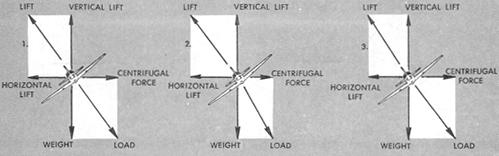
Figure 4-29. Coordinated, slipping, and skidding turn indications.
|
Figure 4-30. Pictorial turn indicators.
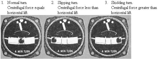 |
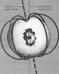
Figure 4-31. Magnetic and geographic poles.
 |
Magnetic Attraction.
A magnet is a piece of metal that has the property of attracting another metal. The force of attraction is greatest at the poles or points near each end of the magnet; and the least attraction is in the area halfway between the two poles. Lines of force flow from each of these poles in all directions, bending around and flowing toward the other poles to form a magnetic field. Such a magnetic field surrounds the Earth, with the lines of force oriented approximately to the north and south magnetic poles (Fig. 4-31).
In flight, allowance must be made for the difference in locations of the geographic and magnetic poles if your course reference is the geographic (true) pole, because the aircraft compass is oriented to the magnetic pole. Lines of equal magnetic declination or "variation" are called isogonic lines, and are plotted in degrees of east and west variation on aeronautical charts. A line connecting points of zero degrees variation is called the agonic line. These lines are replotted periodically on aeronautical charts to correct any change which may have occurred as a result of the shifting of the poles, or any changes caused by local magnetic disturbances. Figure 4-32 shows the irregular pattern of the lines of equal variation in the United States.
Figure 4-32. Lines of equal variation in the United States.
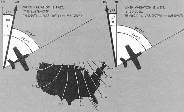 |
Figure 4-33. Magnetic dip.
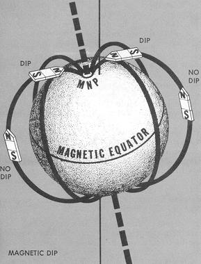 |
Magnetic Dip.
A number of compass errors are caused by deflection of the aircraft
compass needles as they seek alignment with the earth's magnetic lines
of force. Note in Figure 4-33 how lines of force in the earth's field are
parallel to the earth's surface at the magnetic equator, and curve increasingly
downward closer to the magnetic poles. A magnetic needle will tend to assume
the same direction and position as the line of force. Thus, the needle
will be parallel with the Earth's surface at the magnetic equator, but
will point increasingly downward as it is moved closer to the magnetic
pole. This characteristic is known as magnetic dip. You should understand
the relationship between latitude and magnetic dip to be able to effectively
use the standby compass either for normal or emergency operations.