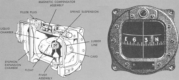
The magnetic compass is a simple self-contained instrument (Fig. 4-34). Two steel magnetized needles are mounted on a float, with a compass card attached around the float. The needles are parallel, with their north-seeking end pointed in the same direction. The compass card has letters for cardinal headings - N. E. S. W. Each 30° interval of direction is represented by a number from which the last zero is omitted. Between the numbers, the card is graduated for each 5°. The float assembly, consisting of the magnetized needles, compass card, and float, is mounted on a pedestal and sealed in a chamber filled with an acid-free white kerosene.
This fluid serves two purposes. Due to buoyancy, part of the weight of the card is taken off the pivot that supports the card. The fluid also decreases oscillation and lubricates the pivot on the pedestal. The pedestal is the mount for the float assembly and compass card. The float assembly is balanced on the pivot, which allows free rotation of the card and allows it to tilt at an angle up to 18°. At the rear of the compass bowl, a diaphragm is installed to allow for any expansion or contraction of the liquid, thus preventing the formation of bubbles or possible bursting of the case.
A glass face is on one side of the compass, and mounted behind the glass is a lubber or reference line by which compass indications are read. Two small compensating magnets are located in the top of the compass case to counteract deviation. These are adjustable by two set screws labeled N-S and E-W.
Figure 4-34. Magnetic compass.
|
Compass Errors.
Variation.
The angular difference between true and magnetic north is referred to as magnetic variation. Figure 4-32 shows how variation is applied to true heading to derive magnetic heading.
Deviation.
The compass needles are affected not only by the earth's magnetic
field, but also by magnetic fields generated when aircraft electrical equipment
is operated and by metal components in the aircraft. These magnetic disturbances
within the aircraft, called deviation, deflect the compass needles from
alignment with magnetic north. Deviation varies according to the electrical
components in use, and the magnetism changes with jolts from hard landings
and installation of additional radio equipment.
To reduce this deviation, each compass is checked and compensated
periodically by adjustment of the N-S/E-W magnets. The errors remaining
after "swinging" the compass are recorded on a compass correction card
mounted in the airplane. To fly compass headings, you refer to the compass
correction card for corrected headings to steer.
Magnetic Dip.
Magnetic dip is the tendency of the compass needles to point down as well as to the magnetic pole. The resultant error is known as dip error, greatest at the poles and zero at the magnetic equator.
Since the compass card is designed to respond only to the horizontal plane of the earth's magnetic field, it turns freely only in the horizontal plane. Any movement of the card from the horizontal results in dip errors. Discussion of these errors is limited to the northern hemisphere; the errors are reversed in the southern hemisphere.
Northerly turning error (Fig. 4-35) is the most pronounced of the dip errors. Due to the mounting of the magnetic compass, its center of gravity is below the pivot point on the pedestal and the card is well balanced in the fluid. When the aircraft is banked, the card is also banked as a result of centrifugal force. While the card is in the banked attitude, the vertical component of the Earth's magnetic field causes the north-seeking ends of the compass to dip to the low side of the turn, giving an erroneous turn indication. This error is most apparent on headings of north and south. When making a turn from a heading of north, the compass briefly gives an indication of a turn in the opposite direction. When making a turn from south, it gives an indication of a turn in the correct direction but at a much faster rate than is actually occurring.
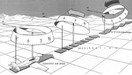
Acceleration error is also due to the dip of the earth's magnetic field. Because of the pendulous-type mounting, the aft end of the compass card is tilted upward when accelerating, and downward when decelerating during changes of airspeed. This deflection of the compass card from the horizontal results in an error which is most apparent on headings of east and west. When accelerating on either an east or west heading (Fig. 4-36), the error appears as a turn indication toward north. When decelerating on either of these headings, the compass indicates a turn toward south. The word "ANDS" (Acceleration-North/Deceleration-South) may help you to remember the acceleration error.
Figure 4-35. Northerly turning error.
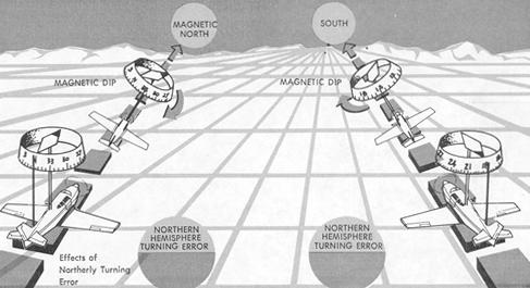 |
Figure 4-36. Acceleration error.
 |
Oscillation Error.
Oscillation error results from erratic movement of the compass card which may be caused by turbulence or rough control technique. During oscillation, the compass is affected by all of the factors discussed. With proper training, the instrument can be effectively used despite the errors.
Figure 4-37. Heading indicator components (vacuum-driven).
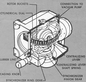 |
Vacuum-Driven Heading Indicator
The diagrammatic illustrations (Figs. 4-37 and 4-38) depict the principal components of the older type vacuum-driven heading indicator still used in many general aviation aircraft.
The vacuum-drive heading indicator is the simplest of many types of gyro-controlled directional indicators designed to provide stable heading reference. Within limits, the directional gyro is not affected by the factors that induce errors in the magnetic compass.
Figure 4-38. Erecting mechanism - vacuum-driven heading indicator.
 |
The operation of the heading indicator (Fig. 4-37) depends upon the principle of rigidity in space of a universally mounted gyroscope. The rotor turns in a vertical plane. Fixed at right angles to the plane of the rotor (to the vertical gimbal) is a circular compass card. Since the rotor remains rigid in space, the points on the card hold the same position in space relative to the vertical plane. As the instrument case revolves about the vertical gimbal, the card provides clear and accurate heading references.
The source of power for the gyro is the engine-driven vacuum pump (or venturi) which sucks air from the rear of the instrument case. This causes air under atmospheric pressure to pass through the filtering system, thence through an air bearing into the hollow vertical gimbal ring. The air then passes through the air nozzle and jets, striking the rotor at a point just above the plane of the horizontal gimbal.
The speed of the rotor may vary from 10,000 to 18,000 rpm, depending on instrument design. For proper operation, the suction gauge reading can be as low as 3.5 and as high as 5.0 inches of mercury, with 4.0 the desired suction. Limits for adjustment of the vacuum are 3.75 and 4.25, or as specified in your aircraft operating hand-book.
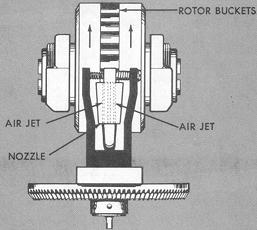
Erecting Mechanism.
During flight, precessing forces displace the rotor from the vertical
plane. To compensate for precession and to provide better airflow distribution
against the rotor buckets, the air is divided by two parallel jets at the
tip of the nozzle (Fig. 4-38).
Each jet strikes the buckets at points equidistant from the center
of the buckets when the rotor is perpendicular in its normal rotating plane.
When the gyro precesses, both jets strike one side of the buckets and cause
the plane of the rotor to again become parallel to the flow of air from
the jets.
Limitations.
The design of the vacuum-driven directional gyro imposes limitations on rotation about the gimbals preventing operation of the instrument in abnormal flight attitudes. If the plane of rotation of the rotor were able to become parallel to the base of the case, it would lose its ability to hold the card in a stationary position, since its axis would be in line with the vertical gimbal and the card would tend to spin with the rotor. The stop, or limiting factor, in the instrument is the caging arm. In the uncaged position, the caging arm rests on the bottom of the vertical gimbal ring and in that position restricts the movement of the vertical gimbal ring about the rotor or the horizontal gimbal. The caging arm is held against the bottom of the vertical gimbal ring by means of a small spring so that rough air cannot cause it to fly up and tumble the instrument. Beyond the normal operating limits - 55° of pitch and bank - when the horizontal gimbal touches the stop, the precessional force causes the card to spin rapidly. This may be corrected by caging, resetting, and uncaging the instrument.
Errors.
The chief cause of precession, causing the card to creep or drift,
is bearing friction. Normal movement of the gimbal rings produces friction,
which is increased if the bearings are worn, dirty, or improperly lubricated.
Other sources of precession error include unbalanced gyro components and
the effect of the earth's rotation. The latter effect depends upon the
position of the instrument in relation to the earth, and is not appreciable
unless a flight involves considerable change in latitude.
An apparent error frequently results from misuse of the magnetic
compass when the directional gyro is set. Unless magnetic deviations are
applied, the indicator may appear to drift several degrees after a turn
is completed. Another common error results from failure to maintain straight-and-level
flight while reading the magnetic compass for the heading to set in the
directional gyro. Errors in the magnetic compass induced by attitude changes
are thus duplicated in the heading indicator.
The instrument should be checked at least every 15 minutes during
flight and reset to the correct heading. An error of no more than 3°
in 15 minutes is acceptable for normal operations.
Caging Mechanism.
The heading indicator can be adjusted by pushing in on the caging
knob to mesh pinion and ring gears, thereby permitting rotation of the
vertical gimbal and card. (Another type of caging mechanism utilizes friction
between rubber and metal rings.) After setting, the gyro is uncaged by
pulling out the caging knob to release the gimbals from the caging mechanism.
Before setting the instrument during ground operations, allow 5 minutes
after engine starting for the gyro to reach operating speed.