If you are among the large group of pilots for whom training cost
is a critical consideration, you will be concerned with minimum equipment
requirements. The expected cost deters many pilots who have access to aircraft
that may be inadequate for weather flying, yet suitable for initial instrument
training. An 85-hp light plane will not perform like the latest supercustom
light twin, nor will it necessarily take you on instruments where and when
you want to go. However, you can acquire substantial basic instrument flying
proficiency in any aircraft having the instruments necessary for control
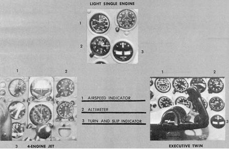
of attitude, altitude, speed, and direction. With an altimeter, airspeed
indicator, and turn-and-slip indicator (needle/ball or turn coordinator),
you have the minimum necessary primary group of instruments. This group
is also called the "partial panel" or "emergency panel."
Note that all of the instrument panels shown in Figure 4-1 include
the same basic group. Regardless of how elaborately equipped an airplane
is, the instrument pilot must know how to use these minimum instruments
necessary for aircraft control.
Most of the aircraft currently manufactured for civilian training
provide the instruments and equipment required by Federal Aviation Regulation
Part 91 for IFR flight. FAR Part 91 also specifies the instruments and
equipment needed for daytime Visual Flight Rules and, when applicable,
for night-time Visual Flight Rules.
Pitot Static Instruments
Six basic flight instruments will be discussed in this chapter. The first three to be considered: pressure altimeter, vertical-speed indicator, and airspeed indicator. Each of these instruments operates in response to pressures through the pitot-static system. Because of the importance of these instruments for safe operation during instrument conditions, you should understand the construction, operation, and use of the pitot-static system and related instruments.
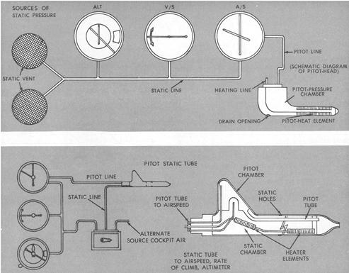
Pitot-static Systems. Two types of systems are available. Both provide a source of static (atmospheric) pressure and impact (ram) pressure to the appropriate instruments. The difference in the systems is largely in the location of the static source (Fig. 4-2).
Figure 4-1. Partial panel (light single-engine, executive twin, 4-engine jet).
|
Of the two systems, the one more recently developed provides for location of the pitot and static sources at separate positions on the aircraft. Impact pressure is taken from the pitot tube, mounted parallel to the longitudinal axis and generally in line with the relative wind. The leading edge of the wing, nose section, or vertical stabilizer are the usual mounting positions, where there is a minimum disturbance of air due to motion of the aircraft. Electric heating elements may be installed to remove ice from the pitot head.
Static pressure is taken from the static line attached to the pitot-static head or to a vent or vents mounted flush with the fuselage or nose section. On aircraft using the flush-type static source, there may be two vents, one on each side of the aircraft. These compensate for any possible variation in static pressure on the vents due to erratic changes in aircraft attitude. The vents are connected by a Y-type fitting. Clogging of the pitot opening by ice or dirt (or failure to remove the pitot cover) affects the airspeed indicator only.
Alternate Source of Static Pressure. In many unpressurized aircraft equipped with a pitot-static tube, an alternate source of static pressure is provided for emergency use. If the alternate source is vented inside the airplane, where static pressure is usually lower than outside static pressure, selection of the alternate source may result in the following instrument indications: the altimeter reads higher than normal; indicated airspeed greater than normal; and the vertical-velocity indicator momentarily shows a climb.
All of these instruments, whether connected to a static source or to both static and pitot lines, operate in response to differences in air pressure that exist within each instrument. The pressure differential is due either to impact and static, or to static and trapped air pressures.
Altitude and Height Measurement
The word "altitude" conveys different meanings to different people involved in aviation. Used by itself, altitude means elevation with respect to any assumed reference level. To the aircraft designer, altitude is significant not so much in the sense of height as in the relationship between altitude and air density, which affects aircraft performance. To the National Ocean Survey, the surveyed altitude of ground obstructions above sea level is of critical importance, as the pilot depends upon the accuracy of chartered information for ground obstruction clearance. Of special importance is the measurement shown on your altimeter, since this is your immediate source of information in the cockpit. As a pilot, you are concerned with all of these meanings of altitude.
Figure 4-2. Pitot-static systems.
 |
Different terms identify specific meanings of altitude (Fig. 4-3) and various methods of height measurement and computation are necessary to determine them. Altimetry thus involves more than simple measurement of height. Your correct use of the altimeter depends upon your understanding of two basic factors: (1) the reference levels from which height is measured; and (2) the operating principles and limitations of the measuring device. The importance of the reference levels will become apparent as you understand the types of altitude and the pressure altimeter, which is the type of measuring device commonly installed in light aircraft.
Types of Altitude. Indicated altitude is the altitude read on your altimeter, assuming that the altimeter is correctly adjusted to show the approximate height of the aircraft above mean sea level (MSL). Altitudes assigned to aircraft in controlled airspace under Instrument Flight Rules are indicated altitudes, except for flights operating in the high altitude route structure.
Figure 4-3. Types of altitude.
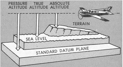 |
Pressure altitude is the altitude read on your altimeter when the instrument is adjusted to indicate height above the Standard Datum Plane. The Standard Datum Plane is a theoretical level where the weight of the atmosphere is 29.92" of mercury as measured by a barometer. As atmospheric pressure changes, the Standard Datum Plane may be below, at, or above sea level. Pressure altitude is important as a basis for determining aircraft performance as well as for assigning flight levels to aircraft operating at high altitude.
Density altitude is pressure altitude corrected for nonstandard temperature. Under standard atmospheric conditions, each level of air in the atmosphere has a specific density and under standard conditions pressure altitude and density altitude identify the same level.
Since aircraft performance data at any level is based upon air density under standard day conditions, such performance data applies to air density levels that may not be identical with altimeter indications. Under conditions higher or lower than standard, these levels cannot be determined directly from the altimeter. For example, your altimeter, set at 29.92", indicates a pressure altitude of 5,000 feet. According to your aircraft flight manual, your ground run will require 790 feet under standard temperature conditions. However, the temperature is 20° C. above standard, and the expansion of air raises the density levels. Using temperature correction data from tables or graphs or by deriving the density altitude with a computer, you find that the density level is above 7,000 feet, and your ground run will be closer to 1,000 feet.
Absolute altitude is height above the surface. This height may
be indicated directly on a radio/radar altimeter, which measures the time
interval of a vertical signal bounced from the aircraft to the ground and
back . Absolute altitude is essential information for flights over mountainous
areas and may be approximately computed from indicated altitude and chart
elevation data.
True altitude is true height above sea level. This is a mathematical
value determined by computer and therefore based upon standard atmospheric
conditions assumed in the computer solution. If the temperature between
the surface and the aircraft does not decrease at the standard rate of
2° per 1,000 feet, or if the pressure at flight level is nonstandard,
reliance on a computer solution to determine obstruction clearance can
be very hazardous.
Pressure Altimeter
The standard pressure altimeter installed in your airplane is
far from satisfactory as an accurate instrument for measuring height, though
the information it provides is essential for aircraft control and for maintaining
terrain clearance and separation from other aircraft under instrument conditions.
The limitations of the instrument are due primarily to the fact that its
design and operation are based upon its response to conditions that rarely
exist. Notwithstanding the limitations, you can use the altimeter as a
satisfactory height-measuring instrument if you understand how it responds
to nonstandard conditions.
Principle of Operation. The pressure altimeter operates through
the response of trapped air within the instrument to changes in atmospheric
pressure. The atmosphere surrounding the earth exerts pressure because
of its weight, decreasing at a predictable rate as altitude increases.
The pressure altimeter is a barometer that senses changes in atmospheric
pressure and, through a gearing mechanism, converts the pressure to an
altitude indication in number of feet (Fig. 4-4).
The conversion is based upon a fixed set of values known as the U.S. Standard Atmosphere. As the following table shows, atmospheric conditions are standard when sea level pressure and temperature are 29.92 inches of mercury and 15° C., with a temperature lapse rate (rate of change with increasing altitude) of 2° per 1,000 feet.
U.S. Standard Atmosphere Values
------------------------------------------------------
Feet Pressure Temperature
(in, of mercury) (degrees Centigrade)
------------------------------------------------------
16,000 16.21 -17
15,000 16.88 -15
14,000 17.57 -13
13,000 18.29 -11
12,000 19.03 -9
11,000 19.79 -7
10,000 20.58 -5
9000 21.38 -3
8000 22.22 -1
7000 23.09 1
6000 23.98 3
5000 24.89 5
4000 25.84 7
3000 26.81 9
2000 27.82 11
1000 28.86 13
Sea Level 29.92 15
------------------------------------------------------
Two essential facts - that conditions are rarely standard and that the altimeter presents you with standard information even when it senses nonstandard conditions - should stress the need for understanding how the altimeter works. The misinformation due to altimeter construction and atmospheric changes must be understood and compensated for.
The basic component of the pressure altimeter is the aneroid wafer (Fig. 4-5). A stack of these hollow, elastic metal wafers expands or contracts as atmospheric pressure changes, and through a shaft and gearing linkage, rotates the pointers on the dial of the instrument. For each pressure level, the aneroid assumes a definite size and causes the hands to indicate height above whatever pressure level is set into the altimeter setting window.
Figure 4-4. Altimeter components.
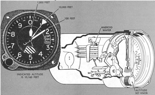 |
The altimeter setting dial provides a means of adjusting the altimeter for nonstandard pressure. For better understanding of the altimeter setting mechanism, assume an altimeter calibrated according to the standard values shown in the previous table, with no provision made for adjusting it for nonstandard conditions. You take off from a sea-level airport where standard conditions exist. On the runway your altimeter reads zero. You land where the field elevation is 2,000 feet and where the surface conditions are also standard. Your altimeter senses 27.82" Hg and reads 2,000 feet as you land.
Figure 4-5. Operation of the altimeter.
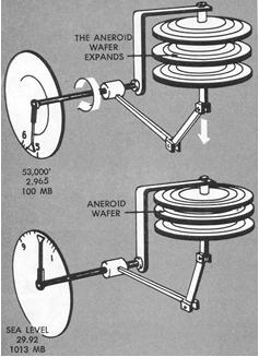 |
Suppose, on the other hand, that the pressure and temperature conditions at the same destination airport had changed to 26.81" Hg/9° C. Your altimeter on touchdown would sense lower pressure and read 3,000 feet. On an instrument approach under these nonstandard conditions, an unadjusted altimeter would indicate 1,000 feet above the runway level on ground impact. By means of a setting knob, the barometric scale on the altimeter setting dial can be rotated so that the altimeter will read "sea level" when nonstandard pressure exists at sea level.
The scale is calibrated from 28.00" to 31.00" to include the extremes in barometric change at sea level. Rotating the setting knob simultaneously rotates the scale and the altimeter hands at a rate of 1" per 1,000 feet of indicated change of altitude. For practical purposes, this ratio can be considered the standard pressure lapse rate below 5,000 feet. Assume that you adjust your altimeter setting dial to 29.92" on an airport at 1,000-foot elevation, and observe an indicated altitude of 1,300 feet. Disregarding other sources of error, your altimeter must be sensing the pressure for which it is calibrated at 1,300 feet. By rotating the knob, you set the altimeter hands to 1,000 feet and the altimeter setting dial rotates to read 29.62" (1" per 1,000 feet equals 0.1" per 100 feet). Thus, rotation of the altimeter setting dial adjusts the altimeter hands to a desired indication for the size of the aneroid at existing pressure.
Effects of nonstandard conditions can result in a difference of as much as 2,000 feet between true and indicated altitude. Temperature variations expand or contract the atmosphere and raise or lower the pressure levels that the altimeter is designed to sense. On a warm day, the pressure level where the altimeter will indicate 4,000 feet is higher than it would be under standard conditions; on a cold day the pressure level is lower than standard. Figure 4-6 shows the relationship between indicated and true altitude with temperature variation.
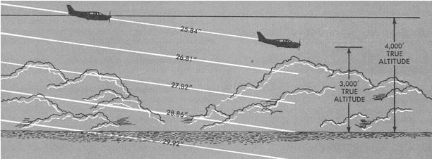
Changes in surface pressure also affect the pressure levels at
altitude, as shown in Figure 4-7. At any level, the effect of lower than
standard pressure on an uncorrected altimeter is to place the aircraft
lower than its altimeter indicates.
The altimeter setting system provides you with the means that
must be used to correct your altimeter for pressure variations. The system
is necessary to ensure safe terrain clearance for instrument approaches
and landings and to maintain vertical separation between aircraft during
instrument weather conditions.
Figure 4-6. Nonstandard temperature and altimeter interpretation.
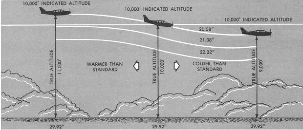 |
Figure 4-7. Nonstandard pressure and altimeter interpretation.
 |
Each weather reporting station takes an hourly measurement of atmospheric pressure and, according to the surveyed elevation of the station, corrects the value obtained to sea level pressure. The resulting altimeter setting broadcast by each Flight Service Station is a computed correction for nonstandard surface pressure only, for a specific location and elevation. Consequently, altimeter indications based upon a local altimeter setting do not necessarily reflect height above mean sea level except in the vicinity of the reporting station and near the surface.
The setting does not compensate for non-standard conditions aloft, especially for the effect of nonstandard temperature. Maintaining the correct reported altimeter settings as you fly cross-country at 5,000 feet indicated altitude does not mean that your aircraft is moving at a constant level of 5,000 feet above mean sea revel. However, since instrument flight in controlled airspace is accomplished at assigned indicated altitudes, aircraft separation is maintained because all aircraft using the same altimeter setting are equally affected by nonstandard conditions at various levels. Altimeter settings are provided periodically to aircraft operating IFR in the low altitude structure by the Air Route Traffic Control Centers. These settings should be used during instrument flight below 18,000 feet MSL.
At or above 18,000 feet MSL, the altimeter should be set at 29.92. Refer to FAR 91.81 {§ 91.81 recodified to § 91.121} for details regarding lowest usable flight levels.
Altimeter Errors. Most pressure altimeters are subject to mechanical, elastic, temperature, and installation errors. Although manufacturing and installation specifications, as well as the periodic tests and inspections required by regulations (FAR 43, Appendix E), act to reduce these errors - any scale error should be noted prior to flight. Scale error may be observed in the following manner:
1. Set the current reported altimeter setting on the altimeter
setting scale.
2. Altimeter should now read field elevation if you are located
on the same reference level used to establish the altimeter setting.
3. Note the variation between the known field elevation and
the altimeter indication. If this variation is in the order of plus or
minus 75 feet, the accuracy of the altimeter is questionable and the problem
should be referred to an appropriately rated repair station for evaluation
and possible correction.
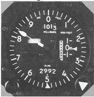
Trends in pressure altimeter design are to be seen in Figures 4-8 and 4-9. Both instruments are similar, differing mainly in presentation of the altimeter setting scales. For improved readability, the instruments provide readout of altitude in "thousands" of feet on the drum, while the single needle indicates altitude in "hundreds" of feet.
Figure 4-8.
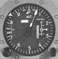 |
Figure 4-9.
 |
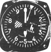
Encoding Altimeter
The encoding altimeter (Fig. 4-10) operates in conjunction with the aircraft's ATC transponder which is described on page 123. The transponder is nothing more than a receiver-transmitter which receives a coded interrogation signal from a round radar site and transmits a coded signal back to the ground site. The interrogation signal from the ground consists of two pulses, either 8 micro-seconds or 21 micro-seconds apart. The transponder receives the pulses and determines the spacing. If the 8 micro-seconds signal is received, the transponder is activated and transmits a "Mode A" signal. If the 21 micro-seconds signal is received, the transponder is activated and will transmit altitude information (a Mode C signal).
Figure 4-10. Encoding altimeter.
 |
In "Mode C" operation, the interrogation signal places the transponder in the attitude reporting mode. When this happens, all codes selected by the transponder are rendered inactive and the encoding altimeter supplies the transponder reply code. This code is related to the aircraft's altitude and is transmitted to the ground site in the same manner as "Mode A." The ground radar alternately interrogates with "Mode A" and "Mode C" signals, thus displaying vertical as well as horizontal and other information on the radar screen, if both "Mode A" and "Mode C" (Mode A/C) are selected. Mode A/C should always be set when flying in an ARTS III environment, above 12,500 feet MSL in controlled airspace (excluding airspace at or below 2,500 feet AGL), or in Terminal Control Areas as specified in FAR Part 91.
There are no specific operating instructions for using an encoding altimeter other than setting it to the local barometric pressure and selecting Mode A/C on the transponder. The computer at the ground radar site as well as the altimeter electronics are referenced to 29.92" Hg. This means that the altimeter always supplies altitude codes based on 29.92" Hg regardless of the altimeter's barometric setting. The ground computer automatically computes the difference between the "29.92 altitude" received from the aircraft and the local barometric pressure. It presents the controller the proper "MSL altitude." Since the altimeter electronics are referenced to 29.92" Hg, changing the altimeter setting does not change the controller's altitude readout.
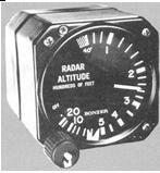
Radar Altimeter
The radar altimeter, also known as radio altimeter, provides a continuous indication of aircraft height above the ground. The system is a "downlooking" device which accurately measures the distance between the aircraft and the highest object on the terrain. The time interval between a transmitted and received radio signal is automatically converted into an absolute altitude reading. The radar altimeter shown in Figure 4-11 has a dial type readout. Another type has a digital presentation. A warning light and aural tone are also provided in this model, which alerts the pilot when the aircraft reaches a preselected altitude.
Figure 4-11. Radar altimeter.
 |
The radar altimeter has three main functions. First, it serves as a ground proximity warning device. Second, it is an accurate cross-check for the barometric altimeter. Third, it gives the pilot rate information on the progress of the final approach and an accurate indication and warning when reaching the "MDA" (Minimum Descent Altitude) or "DH" (Decision height) during instrument approaches.
All radar altimeters operate on a radio frequency of 4300 MHz.