Before any flight, especially a flight into instrument conditions, a thorough check should be made of all instruments and equipment in the airplane. Your airplane flight handbook lists the items to be checked. They may vary as to sequence and content from the checks shown below.
Before Starting Engine. Although the following pre-start check might seem a waste of time, it can reveal conditions or defects which would make starting inadvisable.
1. Appropriate handbooks, enroute charts, approach charts, computer,
and flight log.
2. Radio equipment - switches off.
3. Suction gauge - proper markings.
4. Pitot cover - removed.
5. Airspeed indicator - proper reading.
6. Heading indicator - uncaged if applicable.
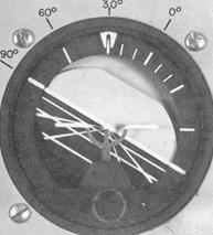
7. Attitude indicator - uncaged if applicable.
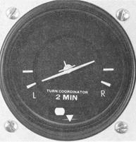
8. Turn coordinator - miniature aircraft level, ball approximately
centered (level terrain).
9. Vertical-speed indicator - zero indication.
10. Magnetic compass - full of fluid.
11. Clock - wind and set to the correct time.
12. Engine instruments - proper markings and readings.
13. De-icing and anti-icing equipment - availability and fluid
quantity.
After Starting Engine. Make the following checks.
1. Suction Gauge or Electrical Indicators - Check the source of power for the gyro instruments. The suction developed should be appropriate for the instruments in that particular aircraft. If the gyros are electrically driven, check the generators and inverters for proper operation.
2. Pitot Head - Heat checked.
3. Magnetic Compass - Check the card for freedom of movement and be sure that the bowl is full of fluid. Determine compass accuracy by comparing the indicated heading against a known heading while the airplane is stopped or taxiing straight. Remote Indicating Compasses should also be checked against known headings.
4. Heading Indicator - Allow 5 minutes after starting engines for the gyro rotor of the vacuum-operated heading indicator to attain normal operating speed. Before taxiing, or while taxiing straight, set the heading indicator to correspond with the magnetic compass heading. Be sure the instrument is fully uncaged if it has a caging feature. Before takeoff, recheck the heading indicator. If your magnetic compass and deviation card are accurate, the heading indicator should show the known taxiway or runway direction when the airplane is aligned with them (within 5°).
Electric gyros should also be set and checked against known headings. Allow 3 minutes for the electric gyro to attain operating speed. A gyrosyn (slaved gyro) compass should be checked for slaving action and its indications compared with those of the magnetic compass.
5. Attitude Indicator - Allow the same times as noted above for
gyros to attain normal rotor speed. If the horizon bar erects to the horizontal
position and remains at the correct position for the attitude of the airplane,
or if it begins to vibrate after this attitude is reached and then slowly
stops vibrating altogether, the instrument is operating properly. If the
horizon bar fails to remain in the horizontal position during straight
taxiing, or tips in excess of 5° during taxi turns, the instrument
is unreliable.
Adjust the miniature aircraft with reference to the horizon
bar for the particular airplane while on the ground. For some tricycle-geared
airplane, a slightly nose-low attitude on the ground will give a level
flight attitude at normal cruising speed.
6. Altimeter - With the altimeter set to the current reported altimeter setting, note any variation between the known field elevation and the altimeter indication. If the variation is in the order of plus or minus 75 feet, the accuracy of the altimeter is questionable and the problem should be referred to an appropriately rated repair station for evaluation and possible correction.
7. Turn Coordinator - During taxi turns, check the miniature aircraft for proper turn indications. The ball should move freely. While taxiing straight, the miniature aircraft should be level.
8. Vertical-Speed Indicator - The instrument should read zero. If it does not, tap the panel gently. If it stays off the zero reading and is not adjustable, the ground indication will have to be interpreted as the zero position in flight.
9. Carburetor Heat - Check for proper operation and return to cold position.
10. Engine Instruments - Check for proper readings.
11. Radio Equipment - Check for proper operation and set as desired.
12. De-Icing and Anti-Icing Equipment - Check operation.
Basic Maneuvers
Instrument flying techniques differ according to airplane type, class, performance capability and instrumentation. The procedures and techniques that follow will, therefore, need to be modified for application to different types of airplanes. Recommended procedures, performance data, operating limitations, and flight characteristics of a particular airplane are available in your airplane flight manual or owner's handbook for study before practicing the flight maneuvers.
The flight maneuvers discussed here assume a single-engine, propeller-driven light airplane with retractable gear and flaps and a panel with instruments representative of those discussed earlier under "Basic Flight Instruments." The sequence of maneuvers in the training curriculum, as well as the time necessary for their mastery, is also flexible. The instrument takeoff, for example, is not required on the flight check for the instrument rating. Whether or not it is worth your study and practice depends upon the flight instruments you have available and the weather conditions in which you expect to fly. With the exception of the instrument takeoff, all of the maneuvers can be performed on "partial panel," with the attitude gyro and heading indicator covered or inoperative.
Straight-and-Level Flight
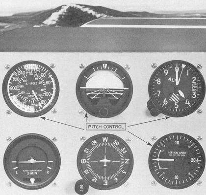
Pitch Control.
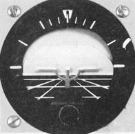
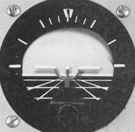
The pitch attitude of an airplane is the angle between the longitudinal axis of the airplane and the actual horizon. In level flight, the pitch attitude varies with airspeed and with load. For training purposes, the latter factor can normally be disregarded in light airplanes. At a constant airspeed, there is only one specific pitch attitude for level flight. At low cruise speeds, the level flight attitude is nose-high (Fig. 5-3); at high cruise speeds, the level flight attitude is nose-low (Fig. 5-4). Figure 5-5 shows the attitude at normal cruise speeds.
Figure 5-3. Pitch attitude and airspeed in level flight - low cruise speed.
|
The pitch instruments are the attitude indicator, the altimeter,
the vertical-speed indicator, and the airspeed indicator.
The attitude indicator gives you a direct indication of pitch
attitude. You attain the desired pitch attitude by raising or lowering
the miniature aircraft in relation to the horizon bar by means of elevator
control. This corresponds to the way you adjust pitch attitude in contact
flight by raising or lowering the nose of the airplane in relation to the
natural horizon. However, unless the airspeed is constant, and until you
have established and identified the level flight attitude for that airspeed,
you have no way of knowing whether level flight, as indicated on the attitude
indicator, is resulting in level flight as shown on the altimeter, vertical-speed
indicator, and airspeed indicator. With the miniature aircraft of the attitude
indicator properly adjusted on the ground before takeoff, it will show
approximately level flight at normal cruise speed when you complete your
level-off from a climb. If further adjustment of the miniature aircraft
is necessary, the other pitch instruments must be used to maintain level
flight while the adjustment is made. Caging and uncaging the attitude indicator
in flight, as well as the limitations of the instrument, have been discussed
in Chapter IV, "Basic Flight Instruments."
In practicing pitch control for level flight, using only the attitude indicator, restrict the displacement of the horizon bar to a bar width up or down, a half-bar width, then a one-and-one-half bar width. Half-, two-, and three-bar-width nose-high attitudes are shown in Figures 5-6, 5-7, and 5-8.
Figure 5-4. Pitch attitude and airspeed in level flight - high cruise speed.
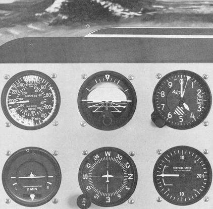 |
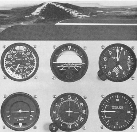
Figure 5-5. Pitch attitude and airspeed in level flight - normal cruise speed.
 |
Your instructor will demonstrate these normal pitch corrections while you compare the indications on the attitude indicator with the airplane's position with respect to the natural horizon. Note that pitch attitude changes for corrections to level flight by reference to instruments are much smaller than those commonly used for contact flight. Note especially that, with the airplane correctly trimmed for level flight, the elevator displacement and the control pressures necessary to effect these standard pitch changes are usually very slight. Just how much elevator control pressure to use is a problem you must solve for yourself, with a few helpful hints.
First, you cannot feel control pressure changes with a tight grip on the controls. Relaxing and learning to control "with your eyes and your head" instead of your muscles usually takes considerable conscious effort during early stages of instrument training.
Second, make the pitch changes smooth and small, yet with a positive pressure. Practice these small corrections until you can make pitch corrections up or down, "freezing" (holding constant) the one-half, full, and one-and-one-half bar widths on the attitude indicator.
Third, with the airplane properly trimmed for level flight, momentarily release all of your pressure on the elevator control when you become aware of tenseness. This will remind you that the airplane is stable and, except under turbulent conditions, will maintain level flight if you leave it alone. One of your most difficult initial training problems will be to resist the impulse to move the controls, even when your eyes tell you that no control change is called for.
Figure 5-6. Pitch correction for level flight - half-bar width.
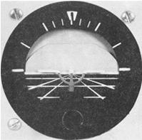 |
Figure 5-7. Pitch correction for level flight - two-bar width.
 |
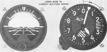
At a constant thrust, any deviation from level flight (except in turbulent air) must be the result of a pitch change. The altimeter, therefore, gives an indirect indication of the pitch attitude in level flight, assuming constant power. Since the altitude should remain constant when the airplane is in level flight, any deviation from the desired altitude shows the need for a pitch change. If you are gaining altitude (Fig. 5-9), the nose must be lowered (Fig. 5-10). How much? And how can it be done by reference to the altimeter alone?
Figure 5-8. Pitch correction for level flight - three-bar width.
 |
The rate of movement of the altimeter needle is as important as its direction of movement in maintaining level flight without the use of the attitude indicator. An excessive pitch deviation from level flight results in a relatively rapid change of altitude; while a slight pitch deviation causes a slow change. Thus, if the altimeter needle moves rapidly clockwise, assume a considerable nose-high deviation from level flight attitude. Conversely, if the needle moves slowly counter-clockwise to indicate a slightly nose-low attitude, assume that the pitch correction necessary to regain the desired altitude is small. As you add the altimeter to the attitude indicator in your cross-check, you will learn to recognize the rate of movement of the altimeter needle for a given pitch change as shown on the attitude indicator.
If you are practicing precision control of pitch in an airplane without an attitude indicator, make small pitch changes by visual reference to the natural horizon, and note the rate of movement of the altimeter. Note the pitch change giving the slowest steady rate of change on the altimeter. Then practice small pitch corrections until you can control them by interpretation and control of the rate of needle movement.
Your instructor may demonstrate an excessive nose-down deviation (indicated by rapid movement of the altimeter needle) and then, as an example, show you the result of improper corrective technique. The normal impulse is to make a large pitch correction in a hurry, but this inevitably leads to overcontrolling: the needle slows down, then reverses direction, and finally indicates an excessive nose-high deviation. The result is tension on the controls, and erratic control response and increasingly extreme control movements. The correct technique, which is slower and smoother, will return the airplane to the desired attitude more quickly, with positive control and no confusion.
Figure 5-9. Using the altimeter for pitch interpretation - altitude increase.
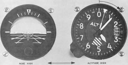 |
Figure 5-10. Pitch correction following altitude increase.
 |
When a pitch error is detected, corrective action should be taken promptly, but with light control pressures and with two distinct changes of attitude: first is a change of attitude to stop the needle movement, second is a change of attitude to return to the desired altitude.
When you observe needle movement indicating an altitude deviation,
apply just enough elevator pressure to slow down the rate of needle movement.
If it slows down abruptly, ease off some of the pressure until the needle
continues to move, but slowly. Slow needle movement means that your airplane
attitude is close to level flight. Add a little more corrective pressure
to stop the direction of needle movement. At this point you are in level
flight; a reversal of needle movement means that you have passed through
it. Relax your control pressures carefully as you continue to cross-check,
since changing airspeed will cause changes in the effectiveness of a given
control pressure. Next, adjust the pitch attitude with elevator pressure
for the rate of change of altimeter needle movement that you have correlated
with normal pitch corrections, and return to the desired altitude.
As a rule of thumb, for errors of less than 100 feet, (Fig. 5-11)
use a half-bar-width correction (Fig. 5-12). For errors in excess of 100
feet (Fig. 5-13), use an initial full-bar-width correction (Fig. 5-14).
Practice predetermined altitude changes using the altimeter alone, then in combination with the attitude indicator.
The vertical-speed indicator gives an indirect indication of pitch attitude and is both a trend and a rate instrument. As a trend instrument, it shows immediately the initial vertical movement of the airplane, which, disregarding turbulence, can be considered a reflection of pitch change. To maintain level flight, use the vertical-speed indicator in conjunction with the altimeter and attitude indicator. Note any "up" or "down" trend of the needle from zero and apply a very light corrective elevator pressure. As the needle returns to zero, relax the corrective pressure. If your control pressures have been smooth and light, the needle will react immediately and slowly, and the altimeter will show little or no change of altitude.
Used as a rate instrument, the lag characteristics of the vertical-speed indicator must be considered.
Lag refers to the delay involved before the needle attains a stable indication following a pitch change. Lag is directly proportional to the speed and magnitude of a pitch change. If a slow, smooth pitch change is initiated, the needle will move, with minimum lag, to a point of deflection corresponding to the extent of the pitch change and then stabilize as the aerodynamic forces are balanced in the climb or descent. A large and abrupt pitch change will produce erratic needle movement and also introduce greater time delay (lag) before the needle stabilizes. Students are cautioned not to "chase the needle" when flight through turbulent conditions produces such erratic needle movements.
In using the vertical-speed indicator as a rate instrument and combining it with the altimeter and attitude indicator to maintain level flight, keep this in mind: the amount the altimeter has moved from the desired altitude governs the rate at which you should return to that altitude. A rule of thumb is to make an attitude change that will result in a vertical speed rate that is approximately double your error in altitude. For example, if off altitude 100 feet, your rate of return should be approximately 200 feet per minute. If off more than 100 feet, the correction should be correspondingly greater, but should never exceed the optimum rate of climb or descent for your airplane at a given airspeed and configuration. A deviation of more than 200 feet per minute from the desired rate of return is considered overcontrolling. For example, if you are attempting to return to an altitude at a rate of 200 feet per minute, a rate in excess of 400 feet per minute indicates overcontrolling. While returning to an altitude, the vertical-speed indicator is the primary pitch instrument. Occasionally, the vertical-speed indicator is slightly out of calibration and may indicate a climb or descent when the airplane is in level flight. If you cannot adjust the instrument, you must take the error into consideration when using it for pitch control. For example, if the needle indicates a descent of 200 feet per minute while in level flight, use this indication as the zero position.
Figure 5-11. Altitude error - less than 100 feet.
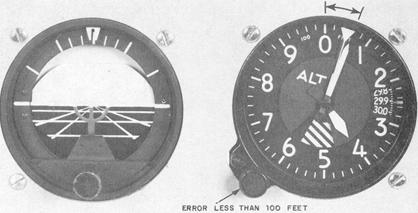 |
Figure 5-12. Pitch correction - less than 100 feet.
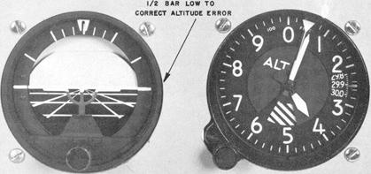 |
Figure 5-13. Altitude error - greater than 100 feet.
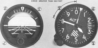 |
Figure 5-14. Pitch correction - greater than 100 feet.
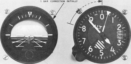 |
The airspeed indicator presents an indirect indication of the pitch attitude. At a constant power setting and pitch attitude, the airspeed remains constant (Fig. 5-15). As the pitch attitude lowers, airspeed increases (Fig. 5-16), and the nose should be raised. As the pitch attitude rises, the airspeed decreases (Fig. 5-17), and the nose should be lowered. A rapid change in airspeed indicates a large pitch change, and a slow change of airspeed indicates a small pitch change. The apparent lag in airspeed indications with pitch changes varies greatly among different airplanes and is due to the time required for the airplane to accelerate or decelerate when the pitch attitude is changed. There is no appreciable lag due to the construction or operation of the instrument. Small pitch changes, smoothly executed, result in an immediate change of airspeed.
Pitch control in level flight is a question of scanning and interpretation
of the instrument panel for whatever information the instruments present
that will enable you to visualize and control pitch attitude. Regardless
of individual differences in scanning technique, all pilots should use
the instruments that give the best information for controlling the airplane
in any given maneuver. They also check the other instruments to aid in
maintaining the important, or primary, instruments at the desired indication.
As noted previously, the primary instrument is the one that gives
the most pertinent information for any particular maneuver. It is usually
the one that you should hold at a constant indication. Which instrument,
for example, is primary for pitch control in level flight? This question
should be considered in the context of specific airplane, weather conditions,
pilot experience, operational conditions, and other factors. Attitude changes
must be detected and interpreted instantly for immediate control action
in high-performance airplanes. On the other hand, a reasonably proficient
instrument pilot in a slower airplane may rely more on the altimeter for
primary pitch information, especially if it is determined that too much
reliance on the attitude indicator fails to provide the necessary precise
attitude information. Whether the pilot decides to regard the altimeter
as primary, or the attitude indicator as primary is a question of which
approach best helps control attitude.
Figure 5-15. Constant power plus constant pitch equals constant airspeed.
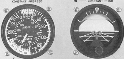 |
Figure 5-16. Constant power plus decreased pitch equals increased airspeed.
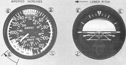 |
Figure 5-17. Constant power plus increased pitch equals decreased airspeed.
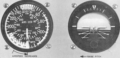 |
In this handbook, the altimeter is normally considered as the primary pitch instrument during level flight.
Bank Control.
The bank attitude of an airplane is the angle between the lateral axis of the airplane and the natural horizon. To maintain a straight-and-level flight path, you must keep the wings of the airplane level with the horizon (assuming that the airplane is in coordinated flight). Any deviation from straight flight resulting from bank error should be corrected by coordinated aileron and rudder pressure.
The instruments used for bank control are the attitude indicator,
the heading indicator, and the turn coordinator (Fig. 5-18).
The attitude indicator shows any change in bank attitude directly
and instantly. On the standard attitude indicator, the angle of bank is
shown pictorially by the relationship of the miniature aircraft to the
artificial horizon bar, and by the alignment of the pointer with the banking
scale at the top of the instrument. On the face of the standard 3" instrument,
small angles of bank can be difficult to detect by reference to the miniature
aircraft, especially if you lean to one side or move your seating position
slightly. The position of the scale pointer is a good check against the
apparent miniature aircraft position. Disregarding precession error, small
deviations from straight coordinated flight can be readily detected on
the scale pointer. The banking index may be graduated as shown in Figure
5-19, or it may lack the 10° and 20° indexes. Refer to Chapter
IV on "Basic Flight Instruments" for application of bank control techniques
to types of attitude indicators other than the one illustrated here. Caging
and uncaging, as well as the banking limitations of various types are covered
in that chapter.
The instrument depicted in Figure 5-19 has a scale pointer that moves in the same direction of bank shown by the miniature aircraft. If, however, your airplane is equipped with the type attitude indicator shown in Figure 4-25 on page 41, you may be bothered by the fact that the scale pointer moves in a direction opposite to the direction of bank shown by the miniature aircraft. A bank indication of 30° to the right of the zero, or nose position, indicates a 30° left banking attitude. Errors due to the construction of this instrument are common and understandable, but the obvious advantage of the attitude indicator is that you get an immediate indication of both pitch and bank attitude in a single glance. Even with the precession errors associated with many attitude indicators, the quick attitude presentation requires less visual effort and time for positive control than do the other flight instruments.
The bank attitude of an aircraft in coordinated flight is shown indirectly on the heading indicator, since banking results in a turn and change in heading. A rapid movement of the heading indicator needle (or azimuth card in a directional gyro indicates a large angle of bank, whereas a slow movement of the needle or card reflects a small angle of bank, assuming the same airspeed in both instances. If you note the rate of movement of the heading indicator for given degrees of bank shown on the attitude indicator, you will learn to look for important bank information on the heading indicator, especially when precession error in the attitude indicator requires a precise check of heading information to maintain straight flight.
Figure 5-18. Instruments used for bank control.
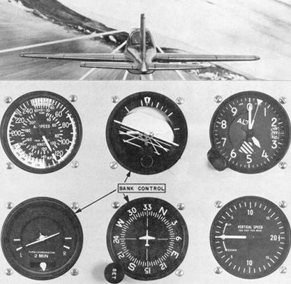 |
When you note deviations from straight flight on the heading indicator, make your correction to the desired heading by using an angle of bank no greater than the number of degrees to be turned. In any case, limit your bank corrections to a bank angle no greater than that required for a standard rate turn. Use of larger bank angles requires a very high level of proficiency, and normally results in overcontrolling and erratic bank control. For heading indicator limitations, refer to the chapter on "Basic Flight Instruments."
The miniature aircraft of the turn coordinator gives you an indirect indication of the bank attitude of the airplane. When the miniature aircraft is level, the airplane is in straight flight. When the miniature aircraft is in a stabilized deflection, the airplane is turning in the direction indicated. Thus, if the ball is centered, a left deflection of the miniature aircraft means the left wing is low and the airplane is in a left turn. Return to straight flight is accomplished by coordinated aileron and rudder pressure to level the miniature aircraft. You must observe the miniature aircraft closely to detect small deviations from the desired position. When the instrument is used to maintain straight flight, control pressures must be applied very lightly and smoothly.
The ball of the turn coordinator is actually a separate instrument, conveniently located under the miniature aircraft because the two instruments are used together. The ball instrument indicates the quality of the turn. If the ball is off center, the airplane is slipping or skidding, and the miniature aircraft under these conditions is erroneous in its indications of bank attitude. Figures 5-20 and 5-21 show the instrument indications for slips and skids, respectively. If the wings are level and the airplane is properly trimmed, the ball will remain in the center, and the airplane will be in straight flight. If the ball is not centered, the airplane is improperly trimmed (or you are holding rudder pressure against proper trim).
Figure 5-19. Bank interpretation with the attitude indicator.
 |
To maintain straight-and-level flight with proper trim, note the direction of ball displacement. If the ball is to the left of center and the left wing is low, apply left rudder pressure (or release right rudder pressure if you are holding it) to center the ball and correct the slip. At the same time apply right aileron pressure as necessary to level the wings, cross-checking the heading indicator and attitude indicator as you center the ball. If the wings are level and the ball is displaced from center, the airplane is skidding. Note the direction of ball displacement and use the same corrective technique as for an indicated slip. Center the ball (left ball/left rudder, right ball/right rudder), use aileron as necessary for bank control, and retrim.
To trim the airplane, using only the turn coordinator, use aileron pressure to level the miniature aircraft and rudder pressure to center the ball. Hold these indications with control pressures, gradually releasing them as you apply rudder trim sufficient to relieve all rudder pressure. Apply aileron trim if available to relieve aileron pressure. With a full instrument panel, maintain a wings-level attitude by reference to all available instruments while you trim the airplane.
Figure 5-20. Slip indication.
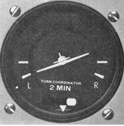 |
Figure 5-21. Skid indication.
 |
Power Control.
Power produces thrust which, with the appropriate angle of attack of the wing overcomes the forces of gravity, drag, and inertia to determine airplane performance.
Power control must be related to its effect on altitude and airspeed, since any change in power setting results in a change in the airspeed or the altitude of the airplane. At any given airspeed, the power setting determines whether the airplane is in level flight, in a climb, or in a descent. If you increase the power while in straight-and-level flight and hold the airspeed constant, the airplane will climb; and if you decrease the power while holding the airspeed constant, the airplane will descend. On the other hand, if you hold altitude constant, the power applied will determine the airspeed.
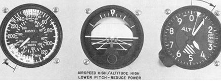
The relationship between altitude and airspeed determines the need for a change in pitch or power. If the airspeed is off the desired value, always check the altimeter before deciding that a power change is necessary. If you think of altitude and airspeed as interchangeable, you can "trade" altitude for airspeed by lowering the nose, or convert airspeed to altitude by raising the nose. If your altitude is higher than desired and your airspeed low (Fig. 5-22), or vice versa, a change in pitch alone may return the airplane to the desired altitude and airspeed. If both airspeed and altitude are high (Fig. 5-23) or if both are low, then a change in both pitch and power is necessary in order to return to the desired airspeed and altitude.
For changes in airspeed in straight-and-level flight, pitch, bank, and power must be coordinated in order to maintain constant altitude and heading. When power is changed to vary airspeed in straight-and-level flight, a single-engine propeller-driven airplane tends to change attitude around all axes of movement. Therefore, to maintain constant altitude and heading, you will need to apply various control pressures in proportion to the change in power. When you add power to increase airspeed, the pitch instruments will show a climb unless you apply forward elevator control pressure as the airspeed changes. When you increase power, the airplane tends to yaw and roll to the left unless you apply counteracting aileron and rudder pressures. The increased speed of cross-check required to keep ahead of these changes varies with the type of airplane and its torque characteristics, the extent of power and speed change involved, and your technique in making the power change.
Figure 5-22. Airspeed low and altitude high (lower pitch).
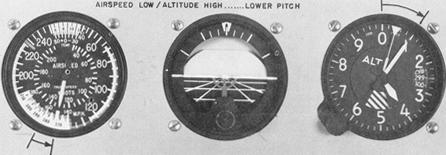 |
Figure 5-23. Airspeed and altitude high (lower pitch and reduce power).
 |
Power control and airspeed changes are much easier when you know in advance the approximate power settings necessary to maintain various airspeeds in straight-and-level flight. However, to change airspeed any appreciable amount, common procedure is to underpower or overpower on initial power changes to accelerate the rate of airspeed change. (For small speed changes, or in airplanes that decelerate or accelerate rapidly, overpowering or underpowering is unnecessary.)
Consider the example of an airplane which requires 23 inches of
manifold pressure to maintain a normal cruising airspeed of 140 knots,
and 18 inches of manifold pressure to maintain an airspeed of 100 knots.
The reduction in airspeed from 140 knots to 100 knots while maintaining
straight-and-level flight, is discussed below and illustrated in Figures
5-24, 5-25, and 5-26.
Instrument indications, prior to the power reduction, are shown
in Figure 5-24. While the basic attitude is established and maintained
on the attitude indicator, specific pitch, bank, and power control requirements
are detected on these primary instruments:
Altimeter - Primary Pitch
Heading Indicator - Primary Bank
Airspeed Indicator - Primary Power
Supporting pitch and bank instruments are shown in the illustrations. Although not shown, the supporting power instrument is the manifold pressure gauge (or tachometer if the propeller is fixed pitch).
As you make a smooth power reduction to a proximately 15" Hg (underpower),
the manifold pressure gauge becomes the primary power instrument (Fig.
5-25). With practice, you will be able to change a power setting with only
a brief glance at the power instrument, by sensing the movement of the
throttle, the change in sound, and the changes in the feel of control pressures.
As the thrust decreases, increase the speed of your cross-check
and be ready to apply left rudder, back elevator, and aileron control pressure
the instant the pitch and bank instruments show a deviation from altitude
and heading. As you become proficient, you will learn to cross-check, interpret,
and control the changes with no deviation of heading and altitude. Assuming
smooth air and ideal control technique, as airspeed decreases, a proportionate
increase in airplane pitch attitude is required to maintain altitude. Similarly,
effective torque control means counteracting yaw with rudder pressure.
Figure 5-24. Straight-and-level flight (normal cruising speed).
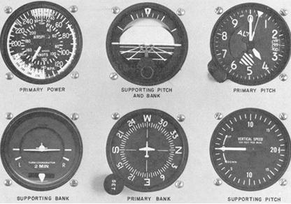 |
Figure 5-25. Straight-and-level flight (airspeed decreasing).
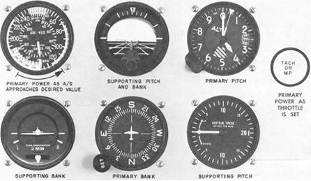 |
As the power is reduced, the altimeter is primary for pitch, the
heading indicator is primary for bank, and the manifold pressure gauge
is momentarily primary for power (at 15" Hg in this example). Control pressures
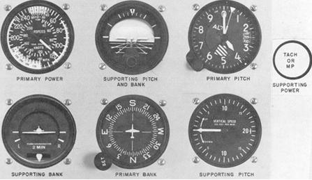
should be trimmed off as the airplane decelerates. As the airspeed approaches
the desired airspeed of 100 knots, the manifold pressure is adjusted to
approximately 18" Hg and becomes the supporting power instrument. The airspeed
indicator again becomes primary for power (Fig. 5-26).
Practice of airspeed changes in straight-and-level flight provides
an excellent means of developing increased proficiency in all three basic
instrument skills, and brings out some common errors to be expected during
training in straight-and-level flight.
Having learned to control the airplane in a "clean" configuration
(minimum drag conditions), you can increase your proficiency in cross-check
and control by practicing speed changes while extending or retracting the
flaps and landing gear. While practicing, be sure you comply with the airspeed
limitations specified in your Aircraft Flight Handbook for gear and flap
operation.
Sudden and pronounced attitude changes may be necessary in order to maintain straight-and-level flight as the landing gear is extended and the flaps are lowered in some airplanes. The nose tends to pitch down with gear extension, and when flaps are lowered, lift increases momentarily (at partial flap settings) followed by a marked increase in drag as the flaps near maximum extension.
Control technique varies according to the lift and drag characteristics of each airplane. Accordingly, knowledge of the power settings and trim changes associated with different combinations of airspeed and gear and flap configurations will reduce your instrument cross-check and interpretation problems.
For example, assume that in straight-and-level flight, an airplane indicates 145 knots with power at 22" manifold pressure/2,300 rpm, gear and flaps up. After reduction in airspeed, with gear and flaps fully extended, straight-and-level flight at the same altitude requires 25" manifold pressure/2,500 rpm. Maximum gear extension speed is 125 knots; maximum flap extension speed is 105 knots. Airspeed reduction to 95 knots, gear and flaps down, can be made in the following manner:
Figure 5-26. Straight-and-level flight (reduced airspeed stabilized).
 |
1. Increase rpm to 2,500, since a high power setting will be
used in full drag configuration.
2. Reduce manifold pressure to 10". As the airspeed decreases,
increase cross-check speed.
3. Make trim adjustments for an increased angle of attack and
decrease in torque.
4. As you lower the gear at 125 knots, the nose may tend to
pitch down and the rate of deceleration increases. Increase pitch attitude
to maintain constant altitude, and trim off some of the back elevator pressures.
If you lower full flaps at this point, your cross-check, interpretation,
and control must be very rapid. A less difficult technique is to stabilize
the airspeed and attitude with gear down before lowering the flaps.
5. Since 18" manifold pressure will hold level flight at 95
knots with the gear down, increase power smoothly to that setting as the
airspeed indicator shows approximately 100 knots, and retrim. The attitude
indicator now shows approximately two-and-a-half-bar width nose high in
straight-and-level flight.
6. Actuate the flap control and simultaneously increase power
to the predetermined setting (25") for the desired airspeed, and trim off
the pressures necessary to hold constant altitude and heading. The attitude
indicator now shows a bar-width nose low in straight-and-level flight at
95 knots.
When you can consistently maintain constant altitude and heading with smooth pitch, bank, power, and trim control during these pronounced changes in trim you will have developed a high level of proficiency in the basic skills involved in straight-and-level flight.
Common Errors.
Heading errors usually result from the following faults:
1. Failure to cross-check the heading indicator, especially during
changes in power or pitch attitude.
2. Misinterpretation of changes in heading, with resulting corrections
in the wrong direction.
3. Failure to note, and remember, a preselected heading.
4. Failure to observe the rate of heading change and its relation
to bank attitude.
5. Overcontrolling in response to heading changes, especially
during changes in power settings.
6. Anticipating heading changes with premature application of
rudder control.
7. Failure to correct small heading deviations. Unless zero error
in heading is your goal, you will find yourself tolerating larger and larger
deviations. Correction of a 1° error takes a lot less time and concentration
than correction of a 20° error.
8. Correcting with improper bank attitude. If you correct a 10°
heading error with a 20° bank correction, you can roll past the desired
heading before you have the bank established, requiring another correction
in the opposite direction. Don't multiply existing errors with errors in
corrective technique.
9. Failure to note the cause of a previous heading error and
thus repeating the same error. For example, your airplane is out of trim,
with a left wing low tendency. You repeatedly correct for a slight left
turn, yet do nothing about trim.
10. Failure to set the heading indicator properly, or failure
to uncage it.
Pitch errors usually result from the following faults:
1. Improper adjustment of the miniature aircraft of the attitude
indicator to the wings-level attitude. Following your initial level-off
from a climb, check the attitude indicator and make any necessary adjustment
in the miniature aircraft for level flight indication at normal cruise
airspeed.
2. Insufficient cross-check and interpretation of pitch instruments.
For example, the airspeed indication is low. Believing that you are in
a nose high attitude, you react with forward pressure without noting that
a low power setting is the cause of the airspeed discrepancy. Increase
your cross-check speed to include all relevant instrument indications before
you make a control response.
3. Uncaging the attitude indicator (if it has a caging feature)
when the airplane is not in level flight. The altimeter and heading indicator
must be stabilized with airspeed indication at normal cruise when you pull
out the caging knob, if you expect the instrument to read straight-and-level
at normal cruise airspeed.
4. Failure to interpret the attitude indicator in terms of the
existing airspeed.
5. Late pitch corrections. Students commonly like to leave well
enough alone. When the altimeter shows a 20-foot error, there is a reluctance
to correct it, perhaps because of fear of overcontrolling. If overcontrolling
is the error, the more you practice small corrections and find out the
cause of overcontrolling, the closer you will be able to hold your altitude.
If you tolerate a deviation for fear of "rocking the boat," your errors
will increase.
6. Chasing the vertical-speed indications. This tendency can
be corrected by proper cross-check of other pitch instruments, as well
as by increasing your understanding of the instrument characteristics.
7. Using excessive pitch corrections for the altimeter evaluation.
Rushing a pitch correction by making a large pitch change generally aggravates
the existing error and saves neither time nor effort.
8. Failure to maintain established pitch corrections. This is
a common error associated with cross-check and trim errors. For example,
having established a pitch change to correct an altitude error, you tend
to slow down your cross-check, waiting for the airplane to stabilize in
the new pitch attitude. To maintain the attitude, you must continue to
cross-check and trim off the pressures that you are holding.
9. Fixations during cross-check. After initiating a heading correction,
for example, you become preoccupied with bank control and neglect to notice
a pitch error. Likewise, during an airspeed change, unnecessary gazing
at the power instrument is common. Bear in mind that a small error in power
setting is of less consequence than large altitude and heading errors.
The airplane will not decelerate any faster while you stare at the manifold
pressure gauge than while you continue your cross-check.
Power errors usually result from the following faults:
1. Failure to know the power settings and pitch attitudes appropriate
to various airspeeds and airplane configurations.
2. Abrupt use of throttle.
3. Failure to "lead" the airspeed when making power changes.
For example, during an airspeed reduction in level flight, especially with
gear and flaps extended, adjust the throttle to maintain the slower speed
before the airspeed reaches the desired speed. Otherwise, the airplane
will decelerate to a speed lower than that desired, resulting in further
power adjustments. How much you lead the airspeed depends upon how fast
the airplane responds to power changes.
4. Fixation on airspeed or manifold pressure instruments during
airspeed changes, resulting in erratic control of both airspeed and power.
Trim errors usually result from the following faults:
1. Improper adjustment of seat or rudder pedals for comfortable
position of legs and feet. Tension in the ankles makes it difficult to
relax rudder pressures.
2. Confusion as to operation of trim devices, which differ among
various airplane types. Some trim wheels are aligned appropriately with
the airplane's axes; others are not. Some rotate in a direction contrary
to what you expect.
3. Faulty sequence in trim technique. Trim should be used, not
as a substitute for control with the wheel (stick) and rudders, but to
relieve pressures already held to stabilize attitude. As you gain proficiency,
you become familiar with trim settings, just as you do with power settings.
With little conscious effort, you trim off pressures continually as they
occur.
4. Excessive trim control. This induces control pressures that
must be held until you retrim properly. Use trim frequently and in small
amounts.
5. Failure to understand the cause of trim changes. If you do
not understand the basic aerodynamics related to the basic instrument skills,
you will be "behind the airplane" continually.