NOTE: The instrument maneuvers presented in Chapter VI are based on a helicopter equipped with a turn coordinator. If the helicopter flown has a turn needle, the descriptions apply if "turn needle" is substituted for "miniature aircraft of turn coordinator."
This chapter describes the performance of basic instrument maneuvers in helicopters. These maneuvers are covered in the same sequence as in the preceding chapter on attitude instrument flying in airplanes. With a few exceptions, the material presented in the first part of the preceding chapter from page 55 through the first column of page 59, is applicable to both airplanes and helicopters. Although the flight maneuvers described in this chapter assume a turbine engine powered single-rotor helicopter, the descriptions can be made to apply to a reciprocating engine powered helicopter by minor changes in terminology. For example, during power control in a reciprocating engine powered helicopter, references should be made to "manifold pressure" rather than "torque."
Helicopter Control
As in airplanes, attitude instrument flying in helicopters is essentially visual flying with the flight instruments substituted for the various reference points on the helicopter and the natural horizon. Control changes required to produce a given attitude by reference to instruments are identical to those used in helicopter VFR flight, and the pilot's thought processes are the same. Unlike airplanes, in helicopters both lift and thrust originate from a single source, the main rotor(s). The helicopter's pitch attitude is controlled by changing the angle of attack of the main rotor disc with cyclic. In straight-and-level flight, pitch attitude changes result in airspeed changes and also cyclic climbs and descents. Power control in a helicopter is accomplished by changing the angle of attack of the individual rotor blades by means of collective pitch. In level flight, changes of power (collective pitch) result in altitude changes if airspeed is held constant, or airspeed changes if altitude is held constant. When making power changes, you must understand and apply the principles of torque; e.g., when power is increased, the helicopter tends to pitch up and yaw right; when power is decreased, the helicopter tends to pitch down and yaw left. Because of this torque effect, you must frequently cross-check the ball of the turn coordinator to ensure proper torque correction (pedal trim).
As in airplanes, aircraft control in helicopters includes pitch attitude control, bank attitude control, power control, and trim.
1. Pitch attitude control is controlling the movement of the
helicopter about its lateral axis. After interpreting the helicopter's
pitch attitude by reference to the pitch instruments (attitude indicator,
altimeter, airspeed indicator, and vertical-speed indicator), cyclic control
adjustments are made to affect the desired pitch attitude with reference
to the natural horizon. In this chapter, the pitch attitudes illustrated
are approximate and will vary with the particular helicopter flown.
2. Bank attitude control is controlling the angle made by the
lateral tilt of the rotor and the natural horizon, or, the movement of
the helicopter about its longitudinal axis. After interpreting the helicopter's
bank instruments (attitude indicator, heading indicator, and turn coordinator),
cyclic control adjustments are made to attain the desired bank attitude.
3. Power control is the application of collective pitch. In
straight-and-level flight changes of collective pitch are made to correct
altitude, if the error is more than 100 feet or the airspeed is off more
than 10 knots. If the error is less than that amount, a slight cyclic climb
or descent should be used.
As a helicopter instrument pilot, you should know the approximate power settings required for your particular helicopter, in various load configurations and flight conditions. For example, on an average day a light single-rotor turbine engine helicopter with the pilot, one passenger, and a full fuel load, requires approximately 62% torque for straight-and-level flight at 90 knots. During flight, minor adjustments from this basic setting should be made to achieve the desired performance.
4. Trim in helicopters refers to the use of the cyclic centering button (if the helicopter is so equipped) to relieve all possible cyclic pressures. Trim also refers to the use of pedal adjustment to center the ball of the turn coordinator. Pedal trim is required during all power changes.
The proper adjustment of collective pitch and cyclic friction will help you relax during instrument flight. Friction should be adjusted to minimize overcontrolling and to prevent creeping, but not applied to such a degree that control movement is limited.
Straight-and-Level Flight
Straight and level unaccelerated flight consists of maintaining
the desired altitude, heading, airspeed, and pedal trim.
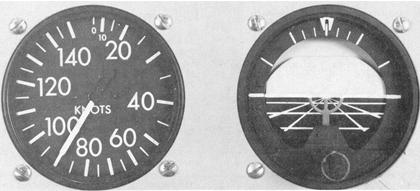
Pitch Control. The pitch attitude of a helicopter is the angular
relation of its longitudinal axis and the natural horizon. If available,
the attitude indicator is used to establish the desired pitch attitude.
In level flight, pitch attitude varies with airspeed and center of gravity.
For training purposes, center of gravity can normally be disregarded in
a light single-rotor helicopter. At a constant altitude and a stabilized
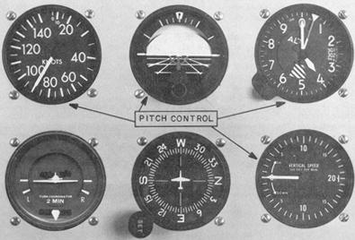
airspeed, the pitch attitude is approximately level (Fig. 6-1). The flight
instruments for pitch control are the attitude indicator, altimeter, vertical-speed
indicator, and airspeed indicator (Fig. 6-2).
Figure 6-1. Airspeed and pitch attitude in level flight.
|
Figure 6-2. Instruments used for pitch control.
 |
The attitude indicator gives a direct indication of the pitch attitude of the of the helicopter. In visual flight, you attain the desired pitch attitude by using cyclic to raise and lower the nose of the helicopter in relation to the natural horizon. During instrument flight, exactly the same procedure is followed in raising or lowering the miniature aircraft in relation to the horizon bar.
You may note some delay between control application and resultant instrument change. This is the normal control lag in the helicopter and should not be confused with instrument lag. The attitude indicator may show small misrepresentations of pitch attitude during maneuvers involving acceleration, deceleration, or turns. This precession error can be detected quickly by cross-checking the other pitch instruments.
If the miniature aircraft is properly adjusted on the ground, it may not require readjustment in flight. If, however, the miniature aircraft is not on the horizon bar after level-off at normal cruising airspeed, adjust it as necessary while maintaining level flight with the other pitch instruments. Once the miniature aircraft has been adjusted in level flight at normal cruising airspeed, leave it unchanged so it will give an accurate picture of pitch attitude at all times.
When making initial pitch attitude corrections to maintain altitude, the changes of attitude should be small and smoothly applied. The initial movement of the horizon bar should not exceed one bar high or low (Fig. 6-3). If further change is required, an additional correction of one-half bar will normally correct any deviation from the desired altitude. This correction (one and one-half bars) is normally the maximum for pitch attitude corrections from level flight attitude. Make corrections of this magnitude, then cross-check the other pitch instruments to determine whether the pitch attitude change is sufficient. If more correction is needed to return to altitude, or if the airspeed varies more than 10 knots from that desired, adjust power.
Figure 6-3. Initial pitch correction at normal cruise - one bar width.
 |
The altimeter gives an indirect indication of the pitch attitude of the helicopter in straight-and-level flight. Since the altitude should remain constant in level flight, deviation from the desired altitude shows a need for a change in pitch attitude and, if necessary, power. When losing altitude, raise the pitch attitude and, if necessary, add power; when gaining altitude, lower the pitch attitude and, if necessary, reduce power.
The rate at which the altimeter moves helps in determining pitch attitude. A very slow movement of the altimeter indicates a small deviation from the desired pitch attitude; while a fast movement of the altimeter indicates a large deviation from the desired pitch attitude. Make any corrective action promptly, with small control changes. Also, remember that movement of the altimeter should always be corrected by two distinct changes. The first is a change of attitude to stop the altimeter; and the second, a change of attitude to return smoothly to the desired altitude. If the altitude and airspeed are more than 100 feet and 10 knots low, respectively, apply power along with an increase of pitch attitude; if the altitude and airspeed are high by more than 100 feet and 10 knots, reduce power along with a lowered pitch attitude.
There is a small lag in the movement of the altimeter; however, for all practical purposes, consider that the altimeter gives an immediate indication of a change, or a need for change in pitch attitude.
Since the altimeter provides the most pertinent information regarding pitch in level flight and is the instrument which should be held constant, it is considered primary for pitch.
The vertical-speed indicator gives an indirect indication of pitch attitude of the helicopter and should be used in conjunction with the other pitch instruments to attain a high degree of accuracy and precision. The instrument indicates zero when in level flight. Any movement of the needle from the zero position shows a need for an immediate change in pitch attitude to return it to zero. If the airspeed varies from that desired by more than 10 knots, a coordinated power change is also required. Always use the vertical-speed indicator in conjunction with the altimeter in level flight. If a movement of the vertical-speed indicator is detected, immediately use the proper corrective measures to return it to zero. The altimeter will usually indicate that there has been little or no change in altitude. If you do not zero the needle of the vertical-speed indicator immediately, the results will show on the altimeter as a gain or loss of altitude.
The initial movement of the vertical-speed needle is instantaneous and indicates the trend of the vertical movement of the helicopter. It must be realized that a period of time is necessary for the vertical-speed indicator to reach its maximum point of deflection after a correction has been made. This time element is commonly referred to as "lag." The lag is directly proportional to the speed and, magnitude of the pitch change. If you employ smooth control techniques and make small adjustments in pitch attitude, lag is minimized and the vertical speed indicator is easy to interpret. Overcontrolling can be stopped by neutralizing the controls, allowing the pitch attitude to stabilize, and then readjusting the pitch attitude by utilizing the indications of the other pitch instruments.
Occasionally, the vertical-speed indicator may be slightly out of calibration ana thus indicate a slight climb or descent when the aircraft is in level flight. If it cannot be readjusted properly, this error must be taken into consideration when using the vertical speed indicator for pitch control. For example, an improperly set vertical-speed indicator may indicate a descent of 100 feet per minute when the helicopter is in level flight. That reading of the instrument would, therefore, indicate level flight, and any deviation from that reading would indicate a change in attitude.
The airspeed indicator gives an indirect indication of helicopter pitch attitude. With a given power setting and pitch attitude, the airspeed will remain constant. If the airspeed increases, the nose is too low and should be raised; if the airspeed decreases, the nose is too high and should be lowered. A rapid change in airspeed indicates a large change in pitch attitude, and a slow change in airspeed indicates a small change in pitch attitude. There is very little lag in the indications of the airspeed indicator. When making attitude changes and some lag is noticed between control application and change of airspeed, cyclic control lag is responsible. Generally, a departure from the desired airspeed, due to an inadvertent pitch attitude change, will also result in a change in altitude. For example, an increase in airspeed due to a low pitch attitude will result in a decrease in altitude. Correction of pitch attitude will regain both airspeed and altitude.
Bank Control. The bank attitude of a helicopter is the angular relation of its lateral axis and the natural horizon. To maintain a straight course in visual flight, you must keep the lateral axis of the helicopter level with the natural horizon. Assuming the helicopter is in coordinated flight, any deviation from a laterally level attitude produces a turn.
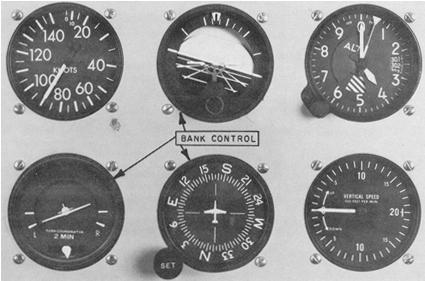
The flight instruments used for bank control are the attitude indicator, heading indicator, and the turn coordinator (Fig. 6-4). The heading indicator is considered primary for bank in level flight.
The attitude indicator gives a direct indication of the bank attitude of the helicopter. For instrument flight, the miniature aircraft and the horizon bar of the attitude indicator are substituted for the actual helicopter and the natural horizon. Any change in bank attitude of the helicopter is indicated instantly by the miniature aircraft. For proper interpretations of this instrument, you should imagine being in the miniature aircraft. If the helicopter is properly trimmed and the rotor tilts, a turn begins. The turn can be stopped by leveling the miniature aircraft with the horizon bar. The ball should always be kept centered through proper pedal trim.
Figure 6-4. Instruments used for bank control.
 |
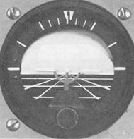
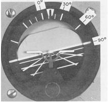
The angle of bank is indicated by the pointer on the banking scale at the top of the instrument (Fig. 6-5). Small bank angles which may not be seen by observing the miniature aircraft, can easily be determined by referring to the banking scale pointer.
Figure 6-5. Bank interpretation with the attitude indicator.
 |
Pitch and bank attitudes can be determined simultaneously on the attitude indicator. Even though the miniature aircraft is not level with the horizon bar, pitch attitude can be established by observing the relative position of the miniature aircraft and the horizon bar.
If the attitude indicator has a caging feature, the instrument should be caged and uncaged only in straight-and-level flight as indicated by the other bank instruments, otherwise it will show a false indication. The attitude indicator may show small misrepresentations of bank attitude during maneuvers which involve turns. This precession error can be immediately detected by closely cross-checking the other bank instruments during these maneuvers. Precession normally is noticed when rolling out of a turn. If, on the completion of a turn, the miniature aircraft is level and the helicopter is still turning, make a small change of bank attitude to center the turn needle and stop the movement of the heading indicator.
In coordinated flight, the heading indicator gives an indirect indication of the helicopter's bank attitude. When a helicopter is banked, it turns. When the lateral axis of the helicopter is level, it flies straight. Therefore, when the heading indicator shows a constant heading, the helicopter is level laterally. A deviation from the desired heading indicates a bank in the direction the helicopter is turning. A small angle of bank is indicated by a slow change of heading; a large angle of bank is indicated by a rapid change of heading. If a turn is noticed, apply opposite cyclic until the heading indicator indicates the desired heading, simultaneously checking the ball for centered position. Make the correction to the desired heading using an angle of bank no larger than the number of degrees to be turned. This correction should not exceed the angle of bank required for a standard rate turn.
During coordinated flight, the miniature aircraft of the turn coordinator gives an indirect indication of the bank attitude of the helicopter. When the miniature aircraft is displaced from level, the helicopter is turning in the direction of the displacement. Thus, if the miniature aircraft is displaced to the left, the helicopter is turning left. Leveling the miniature aircraft with cyclic will produce straight flight. A close observation of the miniature aircraft is necessary to accurately interpret small deviations from the desired position.
Cross-check the ball of the turn coordinator to determine that the helicopter is in coordinated flight. If the rotor is laterally level and torque is properly compensated by pedal pressure, the ball will remain in the center. To center the ball, level the helicopter laterally by reference to the other bank instruments, then center the ball with pedal trim. Torque correction pressures vary as power changes are made. Always check the ball following such changes.