Until comparatively recent times, navigation and voice communications were distinctly separate aspects of cross-country flight. The pilot had to be almost entirely self-dependent. Although ground facilities were sometimes available to provide useful local weather information, the pilot was the BOSS. The pilot had full responsibility for the flight and therefore made all the decisions. Today the pilot is still boss of the aircraft, but modern air travel involves more decisions and responsibilities than can possibly be handled in the cockpit. While the pilot navigates, flight progress is coordinated by radio with a vast team of experts who are also responsible for decisions affecting the flight.
Navigation and communications are thus closely interrelated components of cross-country instrument flight in controlled airspace. The electronic ground and airborne aids, the operational procedures, and the rules are interdependent. Knowledge of the basic radio principles applicable to both communications and navigation equipment will increase your understanding of their use and limitations.
Basic Radio Principles
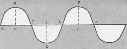
Wave Transmission. Whether transmitted by sound, light, or electricity, energy moves in waves. A wave is a pulse of energy traveling through a medium by means of vibrations from particle to particle. For example, when a stone is dropped into the water, the energy of motion disturbs the water, causing the water to rise and fall. Energy waves travel outward from the source of disturbance, but the water itself does not move outward. This rise and fall above and below the normal undisturbed level can be pictured as a curved line (Fig. 7-1).
The amplitude of a wave is the linear distance measuring the extreme range of fluctuation from the highest or lowest point to the midpoint between them (BH, ID, FJ). A cycle is the interval between any two points measuring the completion of a single wave movement, referenced from any point on the wave to the corresponding point on the succeeding wave (A to E, B to F, C to G). Wavelength is the linear distance of a cycle, measured in units appropriate to the size of a wave (A to E). The frequency of a wave is the number of cycles completed in one unit of time. If 10 cycles are completed in one second, the wave frequency is 10 cycles per second. Since radio wave cycles per unit of time involve very high numbers, radio frequencies are expressed in kilo Hertz* (thousands-of cycles per second) or Megahertz (millions of cycles per second). Thus, a frequency of 1,000 Hz equals 1 kHz, and 1,000 kHz equals 1 MHz.
Figure 7-1. Wave transmission.
|
* The Federal Aviation Administration, in conformance with worldwide practice, has formally adopted the term "Hertz" as the basic unit of frequency, meaning cycle or cycles per second. The standard abbreviations Hz (Hertz); kHz (kilo Hertz); and Mhz (Megahertz) are therefore used in this publication.
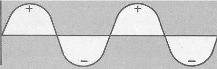
Current is the flow of electrons through a conductor. Direct current (DC) flows only in one direction. Alternating current (AC) flows in one direction during a given time interval, then in the opposite direction for the same interval, reversing continuously. An alternating current can be represented as a continuous change of direction of flow of electrons from positive to negative (Fig. 7-2).
Figure 7-2. Alternating current
 |
Radio Waves. When an electric current flows through a wire, a magnetic field is generated around the wire. When alternating current flows through a wire, the magnetic field alternately builds up and collapses. Radio waves are produced by sending a high-frequency alternating current through a conductor (antenna). The frequency of the wave radiated by the antenna is equal to the frequency, or number of cycles per second, of the alternating current. The velocity of the radiated wave is 186,000 miles per second.
Frequency Bands. Radio frequencies extend from approximately 20 kilo Hertz to over 30,000 Megahertz. Since different groups of frequencies within this range produce different effects in transmission, radio frequencies are classified into groups or frequency bands according to these differences.
Band
Frequency Range
Low-frequency (L/F)........
30 to 300 kHz
Medium-frequency (M/F).....
300 to 3000 kHz
High-frequency (H/F).......
3000 kHz to 30 MHz
Very high frequency (VHF)..
30 to 300 MHz
Ultra high frequency (UHF).
300 to 3000 MHz
Characteristics of Radio Wave Propagation. All matter has a varying degree of conductivity or resistance to radio waves. The Earth itself acts as the greatest resistor to radio waves. Radiated energy that travels near the ground induces a voltage in the ground that subtracts energy from the wave, decreasing the strength (attenuating) of the wave as the distance from the antenna becomes greater. Trees, buildings, and mineral deposits affect attenuation to varying degrees. Radiated energy in the upper atmosphere is likewise affected as the energy of radiation is absorbed by molecules of air, water, and dust. The characteristics of radio wave propagation varying according to the frequency of the radiated signal, determining the design, use, and limitations of both ground and airborne equipment.
Low-Frequency Radio Wave Propagation. A radio wave radiates from an antenna in all directions. Part of the energy travels along the ground (ground wave) until its energy is dissipated. The remainder of the transmitted energy travels upward into space (skywave) and would be lost if it were not reflected in the ionosphere by highly charged particles (ions) caused by the Sun's radiation. Reflection of radio signals back to the Earth permits reception of the signals at varying distances from the transmitter. The distance is determined by the height and density of the ionosphere and the angle at which the radiated wave strikes the ionosphere. The height and density of the ionosphere varies with the time of day, seasons, and latitude since its composition is determined by solar radiation. See Figure 7-3.
The distance between the transmitting antenna and the point where the sky wave first returns to the ground is called the skip distance (Fig. 7-3). The distance between the point where the ground wave can no longer be received and the sky wave returned is called the skip zone. Since solar radiation varies the position and density of the ionosphere, great changes in skip distance occur at dawn and dusk when fading of signals is more prevalent.
High-Frequency Wave Propagation (3,000 kHz to 30 Mhz). The attenuation
of the ground wave at frequencies above approximately 3,000 kHz is so great
that the ground wave is of little use except at very short distances. The
sky wave must be utilized, and since it reflects back and forth from sky
to ground, it may be used over long distances (12,000 miles, for example).
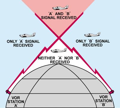
Very High Frequency Propagation (30 to 300 MHz). At frequencies
above about 30 MHz, there is practically no ground wave propagation and
ordinarily no reflection from the ionosphere. Thus, use of VHF signals
is possible only if the transmitting and receiving antennas are raised
sufficiently above the surface of the Earth to allow the use of a direct
wave. This type of radiation is known as "line-of-sight" transmission.
Accordingly, the use of VHF/UHF radio waves is limited by the position
of the receiver in relation to the transmitter (Fig. 7-4).
Figure 7-3. Low-frequency radio wave propagation.
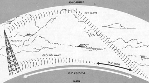 |
Figure 7-4. Line-of-sight transmission.
 |
When using airborne VHF/UHF equipment, it is of the utmost importance that this limitation be understood. The range of VHF/UHF transmission increases with altitude, and may be approximately determined by the following simple method: Multiply the square root of the aircraft altitude in feet by 1.23 to find the VHF/UHF transmission range in nautical miles. For example, an aircraft flying 3,600 feet above flat terrain will receive VHF/UHF signals approximately 74 nautical miles from the transmitter.