These navaids are similar to a standard ILS localizer and are used for nonprecision instrument approaches. Both transmit signals within the frequency range of 108.10 MHz and 111.95 MHz. You will use essentially the same pilot techniques and procedures in executing SDF and LDA approaches that you use in no-glide-slope localizer approaches. Back course approaches may be associated with either SDF or LDA.
The SDF (Simplified Directional Facility) (Fig. 7-35) provides a final approach course similar to the ILS localizer described earlier in this chapter. A clear understanding of the ILS localizer and the additional factors given in the following paragraphs completely describe the operational characteristics and use of the SDF.
The SDF course may or may not be aligned with the runway and the course may be wider than a standard ILS localizer, resulting in less precision. Usable off-course indications are limited to 35° either side of the course centerline. Instrument indications in the areas between 35° and 90° are not controlled and should be disregarded.
The SDF antenna may be offset from the runway centerline. Because of this, the angle of convergence between the final approach course and the runway bearing should be determined by reference to the instrument approach chart. This angle is usually not more than 3°. You should always note this angle since the approach course originates at the antenna site, and an approach continued beyond the runway threshold would lead the aircraft to the SDF offset position rather than along the runway centerline.
The SDF signal emitted from the transmitter is fixed at either 6° or 12° as necessary to provide maximum flyability and optimum course quality. Identification consists of a three letter identifier transmitted in code on the SDF frequency. The identifier for Ponca City Muni SDF is AYQ.
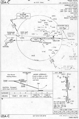
The LDA (localizer-type directional aid) (Fig. 7-36) is of comparable utility and accuracy to a localizer but is not part of a complete ILS. The LDA course width is between 3° and 6° and thus provides a more precise approach course than the similar SDF installation which may have a course width of 6° or 12°. The LDA course is not aligned with the runway; however, straight-in minima may be published where the angle between the runway centerline and the LDA course does not exceed 30°. If this angle exceeds 30°, only circling minima are published. The procedure depicted in Figure 7-36 is an example of this condition. The identifier is three letters preceded by "I," transmitted in code on the LDA frequency.
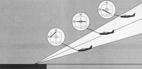
Figure 7-34. Glide slope receiver indications.
|
Figure 7-35. SDF approach procedure chart.
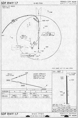 |
Figure 7-36. LDA approach procedure chart.
 |