Static, whether it originates away from the aircraft in lightning discharges or from electrostatic discharges from the aircraft surfaces, distorts the radio wave and interferes with normal reception of both communications and navigation signals. Low-frequency airborne equipment is particularly subject to static disturbance. Signals in the higher frequency bands are static-free.
Precipitation static occurs when static electricity is generated on various aircraft surfaces in flight and is discharged onto other surfaces or into the air. An aircraft generally accumulates little or no static charge when flying in clear atmosphere. But an aircraft flying in particle-laden air may encounter precipitation static because of charged particles that (1) adhere to the aircraft, (2) create a charge through frictional contact, or (3) divide into charged fragments on impact with the aircraft surfaces.
At the lower altitudes and in moderate to heavy rain, precipitation static is common. It is often accompanied by St. Elmo's Fire, a corona discharge which lights up the aircraft surface areas where maximum static discharge occurs.
Precipitation static is also common in very high clouds or in dust storms, where high winds pick up and carry substantial amounts of solid particles. It can also result from atmospheric electric fields in thunderstorm clouds. Ice crystal static is encountered in cirrus clouds, or in altostrautus and nimbostratus clouds in the winter.
Frequency Interference. Omni and localizer receivers used for
enroute navigation and instrument approaches are susceptible to interference
from FM radios which operate in the VHF frequency range. The frequency
oscillations in a portable FM radio operated in an aircraft will be picked
up by the aircraft navigation receivers, distorting the navigation receiver
information.
Additional irregularities in radio wave propagation, of particular
significance in their effect on low-frequency receivers, will be discussed
in connection with the use of the radio compass.
Transmission and Reception of Radio Signals
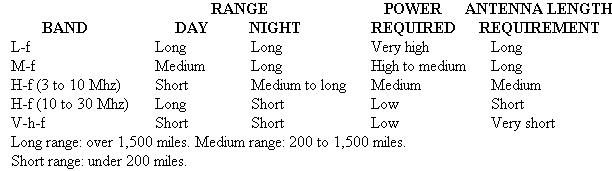
Some of the radio signal transmission characteristics related to ground and airborne equipment and its use are shown in Figure 7-5.
Basic Communication Equipment. In order to transmit messages from one location to another by radio, the following basic equipment is needed (Fig. 7-6):
1. A transmitter to generate radio frequency (r-f) waves.
2. A microphone (or key) to control these energy waves.
3. A transmitting antenna suitable for radiation of the radio
frequencies used.
4. A suitable receiving antenna to intercept some of the radio
frequency waves.
5. A receiver to change the intercepted radio frequency waves
into audio frequency waves.
6. A speaker, or earphones, to change the audio frequency waves
into audible sound.
Basic Navigation Equipment. In order to transmit navigation signals from a ground facility to airborne navigation instruments, the following basic equipment is needed:
1. Signal-forming components to determine the character of the
radio frequency signals generated.
2. A transmitter, to generate the radio frequency waves.
3. Transmitting antennas, suitable for radiation of the radio
frequency signals used.
4. A receiving antenna, or antennas, to intercept the radio
frequency signals.
5. Aircraft receiver components, to select and interpret the
navigation signals.
6. Instruments and devices for visual-audio presentation of
radio navigation information.
The simplified diagram in Figure 7-7 shows how the navigation and communications equipment, both ground and airborne, are related.
Modifying the Radiated Signal. In order to use the radiated signal for communicating information, it is necessary that the signal be modified by the information to be transmitted. The modification can be done either by interrupting the signal (as in morse code), or by modulating the signal (Fig. 7-8). An unmodulated signal is called a continuous wave (cw). A modulated signal is commonly called a modulated carrier wave (mcw). Figure 7-9 illustrates a continuous wave, an amplitude modulated wave, and a frequency modulated wave.
Receiving the Radiated Signals. Radio waves set up currents in receiving antennas, just as an alternating current is set up in any conductor placed near another conductor that carries alternating current. Tuning is the selection of the desired signal (frequency) and rejection of the undesired signals (Fig. 7-10). The tuning circuit in the receiver is adjusted to resonance at the frequency of the desired signal. Other frequencies are rejected by the tuning circuit, and the selected signal is allowed to flow to an amplifier which increases the strength of the signal. If the signal being received is a modulated carrier wave, the useful information which it carries must be detected. This process is called demodulation and is accomplished by the detector.
Figure 7-5. Transmission characteristics of radio signals.
|
 |