In the broad sense of the term, radio navigation includes any method by which a pilot follows a predetermined flight path over the Earth's surface by utilizing the properties of radio waves. The navigation can be conducted by any one or any combination of the following three basic systems:
1. Self-contained air borne systems entirely independent of ground
facilities. The Doppler radar navigation system currently used for long
overwater and transpolar flights is an example.
2. Ground facilities that continuously monitor and determine
the exact aircraft position, on the basis of which the pilot is given navigational
guidance by radio communications. Ground-controlled radar navigation is
becoming increasingly important to instrument flight operations. Long range
radar operated by Air Route Traffic Control Centers (ARTCC) can provide
continuous navigational guidance to aircraft operating along most of the
routes between major metropolitan terminals.
3. A combination of ground and airborne equipment, by means
of which the ground facilities transmit signals to airborne instruments.
The pilot determines and controls ground track on the basis of the instrument
indications.
The navigation systems in common use today are a combination of VOR (very high frequency omnidirectional range), and additional electronic aids and ground-controlled radar.
Very High Frequency Omnirange
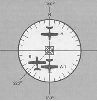
The VOR, or omnirange, is the primary navigation facility for civil aviation in the National Airspace System. As a VHF facility, it eliminates atmospheric static interference and other limitations associated with the older low-frequency facilities that VOR has replaced. The VOR generates directional information and transmits it by ground equipment to the aircraft, providing 360 magnetic courses TO or FROM the VOR station. These courses are called radials and are oriented FROM the station (Fig. 7-11). For example, aircraft A (heading 180°)-is inbound on the 360 radial; after crossing the station, the aircraft is outbound on the 180 radial at A-1. Aircraft B is shown crossing the 225 radial. Similarly, at any point around the station, an aircraft can be located somewhere on a VOR radial.
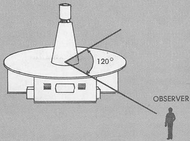
Principles of Operation. VOR operation is based upon the principle that the phase difference between two AC voltages may be used to determine azimuth location. The principle may be more readily visualized by imagining two light signals, both at the same geographic position. The first light is a flashing (reference) signal, visible from any point around the compass. The second light is a narrow beam (variable signal) that rotates continuously at a specific rate. Thus, if you are at any point around the circle, you will see the rotating beam only at the instant it sweeps past your position. Assume that the reference light flashes only when the rotating (variable) beam passes through magnetic north to indicate that the two signals are "in phase." If the rotating beam completes one revolution per minute, you can determine your bearing to the light sources from any point around the compass rose by noting the time interval between your observations of flashing and beam signals. For example, if the two signals are in phase at north (flashing), and you see the rotating beam 20 seconds later, the variable signal has made 20/60 of a revolution. Thus, you must be viewing the beam from a position on the 120 radial (20/60 times 360°, equals 120°), as shown in Figure 7-12. In terms of azimuth, the reference and variable signals are 120° "out of phase."
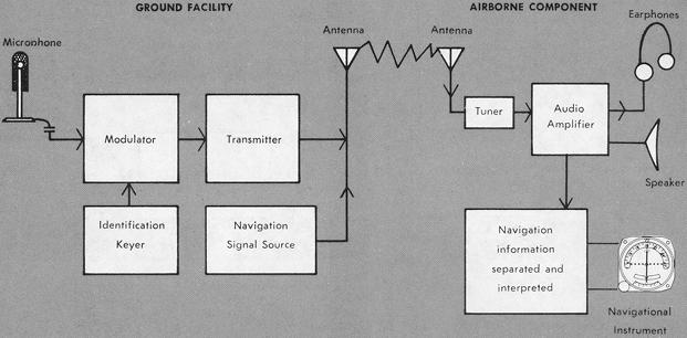
Figure 7-7. Basic navigation equipment.
|
Figure 7-8. Amplitude modulation.
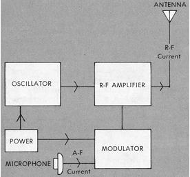 |
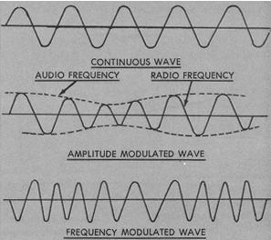
Figure 7-9. Wave modulation.
 |
VOR Transmitter. The VOR transmitter uses the same principle of phase comparison, rotating a signal electrically at 1,800 revolutions per minute. There are two navigation signal components contained in the transmitted signal. One of these signals has a constant phase at all points around the VOR and is called the reference signal. In all directions other than magnetic north, the two signals are out of phase. The omni receiver measures the phase difference electronically and presents the information to indicate bearing.
Figure 7-10. Transmission and reception of radio signals.
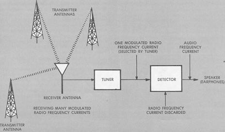 |
Figure 7-11. VOR radials.
 |
In addition to the navigation signals radiated by the VOR, provision
is also made-for voice transmission and automatic identification of the
facility on the same radio frequency.
The VOR ground equipment is easily identified from the air as
a small low building topped with a flat white disc upon which are located
the antennas and a fiberglass antenna shelter (Fig. 7-13).
Figure 7-12. Variable and reference phase relationship - VOR.
 |
The equipment includes an automatic monitoring system that is activated when the signal is interrupted or the phasing is changed. The monitor automatically turns off defective equipment, turns on the standby transmitter, and sounds an alarm in the control room, ensuring continuous reliable service to the users.
Figure 7-13. VOR transmitter.
 |
VOR Class Designations and Frequencies. Omniranges are classified according to their operational uses. The standard VOR facility has a power output of approximately 200 watts, with a maximum usable range depending upon the aircraft altitude, class of facility, location and siting of the facility, terrain conditions within the usable area of the facility, and other factors. Above and beyond certain altitude and distance limits, signal interference from other VOR facilities and signal weakening make the signal unreliable. Areas of confusion between VOR stations can be recognized by an aural squeal and oscillation of the visual indicators in the aircraft.
VOR facilities operate within the 108.0 - 117.95 MHz frequency band. Frequency assignment between 108.0 and 112.0 MHz is even tenth decimals to preclude any conflict with ILS localizer frequency assignment. Between 112.0 and 117.95 MHz the assignment may be either even or odd tenth decimals. H-VORs and L-VORs have a normal usable distance of 40 nautical miles below 18,000 feet. T-VORs are short-range facilities which have a power output of approximately 50 watts and a usable distance of 25 nautical miles at 12,000 feet and below. T-VORs are used primarily in terminal areas, on or adjacent to airports, for instrument approaches.
VOR Irregularities. Minor irregularities in VOR signals consist of course shifting, and may be slightly affected by the altitude of the aircraft. Slow movement of the deviation needle on the aircraft instrument is called course bends; fast deviations of the needle are called course scalloping. When preparing to fly over unfamiliar routes, you can check for VOR irregularities by referring to the appropriate flight-planning publications. These occasional defects are identified by FAA technical specialists to provide pilots with information on the current status of all VOR facilities. Enroute radials published as usable will not be displaced more than 2.5° from the theoretical location of the radial (allowable tolerance, 1.5° for radials published for VOR approaches).
VOR Facility Information Itemized.
1. Frequency range - 108 - 117.95 MHz.
2. Course information - all directions: radials named FROM the
VOR.
3. Coverage - at least 40 miles at normal minimum IFR altitudes.
4. Identification - standard 3-letter code every 5 seconds,
or a combination of code and voice identification, with voice every 15
seconds.
5. Voice communication - the VOR can be used for normal voice
communication without interference with the navigation information being
radiated.
6. Heading insensitivity - the VOR information received by an
aircraft is not influenced by aircraft attitude or direction of flight.