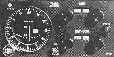
VOR signals can be received by a variety of airborne equipment. Tuning equipment and visual indicators representative of current design are shown in Figure 7-14. Irrespective of differences in dial design, method of tuning, separation of receiver components, and multipurpose designs, all VOR receivers have at least the essential components shown in the NAV/COMM receiver illustrated in the figure.
Figure 7-14. VOR receiver.
|
The components of a VOR receiver can be described as follows:
1. Frequency selector. The frequency selector may be a knob or
knobs or "crank," manually rotated to select any of the frequencies between
108.0 - 117.95 MHz.
2. Course selector. By turning the OBS (Omni Bearing Selector),
the desired course is selected. This may appear in a window or under an
index.
3. Course deviation indicator (CDI). The deviation indicator
is composed of a dial, and a needle hinged to move laterally across the
dial. The needle centers when the aircraft is on the selected radial or
its reciprocal (Fig. 7-15). Full needle deflection from the center position
to either side of the dial indicates the aircraft is 10° or more off
course. assuming normal needle sensitivity.
Figure 7-15. Course deviation indicator.
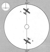 |
4. TO/FROM indicator, also called "sense indicator" and "ambiguity
indicator." The TO/FROM indicator shows whether the selected course will
take the aircraft TO or FROM the station. It does NOT indicate whether
the aircraft is heading to or from the station (Fig. 7-16).
5. Flags, or other signal strength indicators. The device to
indicate a usable or an unreliable signal may be an "OFF" flag that retracts
from view when signal strength is sufficient for reliable instrument indications,
or insufficient signal strength may be indicated by a blank TO/FROM window.
VOR flight procedures will be discussed in Chapter VIII, "Using the Navigation Instruments." VOR approach procedure charts are described in Chapter X, "The Federal Airways System and Controlled Airspace."