Used in conjunction with the nationwide VOR system, distance measuring equipment (DME) has made it possible for you to know the exact geographic position of your aircraft immediately by observation of your VOR and DME indicating equipment. Without DME, you can determine your position by triangulation methods using a single VOR receiver, dual VOR receivers, or a combination of VOR receiver(s) and low-frequency equipment. With DME and VOR equipment in combination, direct reading instruments tell you the distance and bearing to or from the station.
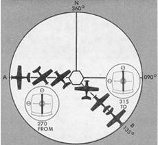
Figure 7-16. To/From indicator.
|
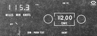
DME Equipment and Operating Principle. The aircraft transmits an interrogating signal made up of a pair of RF pulses, which is received by the DME transponder antenna at the ground facility. The signal triggers ground receiver equipment, and a second pair of pulses is generated and transmitted through the DME transponder antenna back to the interrogating aircraft. The airborne DME interrogating and indicating equipment measures the elapsed time between the second interrogating and reply pulses and converts this time measurement into a mileage, groundspeed, or time readout on the instrument panel. The mileage readout is the direct distance from the aircraft to the DME ground facility and is commonly referred to as slant-range distance. The difference between a measured distance on the surface and the DME slant-range distance is known as slant-range error and is smallest at low altitude and long range. This error is greatest when the aircraft is directly over the ground facility, at which time the DME receiver will display altitude in nautical miles above the facility. Slant-range error is negligible if the aircraft is one mile or more from the ground facility for each 1,000 feet of altitude above the elevation of the facility. Lightweight DME equipment is reported by manufacturers to be accurate within plus or minus one-half mile or three percent of the distance, whichever is greater. Operation of the airborne equipment is simple, as illustrated in Figure 7-17. This model features a selector switch and digital readout which allows the pilot to obtain distance, groundspeed, or time-to-facility.
Area Navigation
Area navigation (RNAV) allows a pilot to fly a selected course to a predetermined point without the need to overfly ground-based navigation facilities. RNAV systems include doppler radar, inertial navigation system (INS), very low frequency (VLF), and the course line computer. The course line computer is the RNAV system which the general aviation pilot is most likely to use.
Figure 7-17. DME indicator.
 |
The course line computer is based on azimuth and distance information generated by the present VORTAC system. It is also called the "Rho-Theta" system. Rho (distance) is derived from the distance measuring feature of the VORTAC, and Theta (bearing) information is derived from the azimuth feature. As shown in Figure 7-18, the value of side (A) is the measured DME distance to the VORTAC. Side (B), the distance from the VORTAC to the waypoint, and angle (1), the bearing from the VORTAC to the waypoint, are set in the cockpit control. The bearing from the VORTAC to the aircraft, angle (2), is measured by the VOR receiver. The airborne computer compares angles (1) and (2) and determines angle (3). With this information, the computer, by means of simple trigonometric functions, continuously solves for side (c), which is the distance in nautical miles and magnetic course from the aircraft to the waypoint. This is presented as guidance information on the cockpit display.
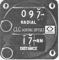
Advisory Circular 90-45A, which sets forth the guidelines for the implementation of area navigation, defines a waypoint as, "...a predetermined geographical position used for route-definition and/or progress-reporting purposes that is defined relative to a VORTAC station position." Waypoints are also defined by latitude and longitude coordinates for the use of airborne self-contained systems not dependent on VORTAC inputs. With the course line computer, the pilot effectively moves or off-sets the VORTAC to a desired location. A " phantom station" is created by setting the distance (Rho) and the bearing (Theta) of the waypoint from a convenient VORTAC, in the appropriate windows of the waypoint selector or "off-set control" (Figure 7-19).
The advantages of the VORTAC area navigation system stem from the ability of the airborne computer to, in effect, locate the VORTAC wherever convenient, if it is within reception range (Figure 7-20). A series of these "phantom stations" or waypoints make up an RNAV route. A number of RNAV routes have been established in the high altitude structure. High altitude RNAV routes are depicted on the "RNAV Enroute High Altitude Charts." In addition to the published routes, you may fly a random RNAV route under IFR if it is approved by ATC. RNAV Standard Instrument departures (SIDs) and Standard Terminal Arrival Routes (STARs) are contained in the SID and STAR booklets.
Figure 7-18. Course line computer geometry.
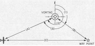 |
Figure 7-19. Waypoint selector or "off-set control"
 |
RNAV approach procedure charts. such as that depicted in Figure 7-21, are also available. You will note that the waypoint identification boxes contain the following information: waypoint name, coordinates, frequency, identifier, radial-distance (facility to waypoint), and reference facility elevation. The initial approach fix (IAF), final approach fix (FAF), and missed approach point (MAP) are labeled. Since these are non-precision approaches, minimums appropriate to such approaches apply. To fly either an RNAV route or to execute an RNAV approach, under IFR, your aircraft must have RNAV equipment which meets the standards set forth in FAA Advisory Circular 90-45A.
Although cockpit displays of guidance information vary, the displacement of a vertical reference means distance from a selected track in nautical miles and not angular displacement. The guidance instrument in one model, Figure 7-22, resembles a conventional VOR course deviation indicator. The familiar CDI needle serves as a course line computer indicator in the CLC (course line computer) mode. A lateral deflection of the needle indicates nautical miles right or left of the selected course. Each dot on the horizontal scale may have any value such as 0.5, 1, 2, or 10 nautical miles. A DME indicator gives distance to the waypoint.
Vertical as well as horizontal guidance is provided in some installations. For example, one manufacturer has designed an Ascent Descent Director (ADD), which combined with the basic two-dimensional RNAV system, provides vertical guidance information similar to a glide slope. With this equipment, a waypoint can be selected not only at a desired surface location but also at a desire altitude. Thus, you can fly a predetermined vertical profile to a preselected point in space.