The low-frequency nondirectional radio beacon, or homing, facility was one of the earliest electronic navigation aids adopted by the FAA. Homing beacons are installed at various locations to provide either navigation fixes or homing points. The typical homing beacon facility incorporates a low-frequency transmitter and an associated antenna system that provides a non-directional radiation pattern. The transmitter, operating in the frequency range between 200-415 kHz, is amplitude modulated with a 1,020 Hz audio tone to provide coded identification.
Types of "H" Facilities. There are four types of nondirectional homing facilities in use:
1. HH facilities have a power output of 2,000 or more watts and
a reception range of 75 nautical miles; they are generally used with overwater
routes.
2. H facilities have a power output of 50 to 1999 watts and
a reception range of 50 nautical miles.
3. MH facilities have a power output of less than 50 watts and
a reception range of 25 nautical miles.
4. ILS compass locator facilities have a power output of less
than 25 watts and a reception range of 15 nautical miles. They are designated
as LOM (Outer Locator) and LMM (Middle Locator), appropriate to the outer
and middle beacon sites where they are located.
Principles of ADF Receiver Operation. The automatic direction finder (ADF) used with the nondirectional homing beacon is a radio receiver that determines the bearing from the aircraft to the transmitting station. Use of the "H" facility requires a directional antenna for reception of the signals. A directional antenna is one that conducts radio signals more efficiently in one direction than in others. A single-wire vertical antenna ("sense" antenna) is nondirectional in that it conducts received or transmitted signals with equal efficiency in all directions. A loop of wire, or two wires suitably connected, have important directional characteristics for transmission or reception.
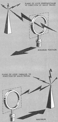
Directional antennas for ADF receivers are usually in the form of loops which extract a portion of the signal energy. The position of the plane of the loop in reference to the station determines the induced voltages in the sides of the loop and the strength of the signal received through the antenna. Maximum signal strength is received when there is a maximum difference in the induced voltages in the sides of the loop (Fig. 7-26). Minimum signal strength (or null) exists when equal voltages are induced in both sides of the loop simultaneously and no current passes through the receiver.
Sense Antenna. A sense antenna is also necessary for the operation of automatic direction finding equipment because the loop antenna, although it senses direction by comparison of voltages, cannot sense whether the station is behind or ahead, or to the left or right. This characteristic of loop reception is called ambiguity. By combining the properties of the loop antenna with those of a sense antenna, the direction of the incoming signal is resolved so that the ADF indicator continuously shows the relative bearing of the transmitting station to which tuned.
ADF Receiving Equipment. Several different types of automatic direction finders are available. One type indicates only relative bearing to the station; another indicates both relative bearing and magnetic bearing to the station directly on the same dial. Some indicators have rotating dials and pointers, others have fixed dials. The receiver may include a tuning meter, and a manual control position on the function switch. The essentials are common to all ADF receivers, however, regardless of design detail. In addition to receiving navigation signals, ADF equipment also receives voice communications from L/MF transmitters.
A typical older type light plane ADF receiver and indicator (Fig. 7-27) may include the following components:
1. Frequency band selector, permitting the use of any ground
transmitter, within the frequency range shown. Commercial broadcasting
stations as well as the nondirectional homing beacons can be used.
2. Function switch, to select either the sense antenna for tuning,
or loop antenna for manual or automatic direction finding.
3. Tuning crank.
4. On-off switch and volume control.
5. CW switch, used to obtain better reception of unmodulated
signals. The switch actuates a signal in the receiver which is added to
the incoming signals producing a continuous tone. On some receivers, the
switch is labelled "BFO," meaning "Beat Frequency Oscillator."
Figure 7-26. Loop antenna.
|
6. Loop switch which is operative when function switch is in
"Loop" position. It is used to rotate the loop left or right to more accurately
tune in weak stations and also to identify the aural null position of the
incoming signal.
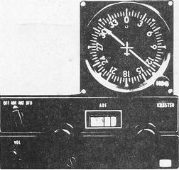
The modern crystal-controlled ADF receiver with digital tuning
(Fig. 7-28) eliminates manual tuning and the tuning meter. In the model
shown, any frequency from 200 kHz to 1699 kHz, in increments of 1 kHz,
may be selected. When the function switch is set to ADF, the bearing pointer
of the indicator shows the relative bearing to the station. During ANT
operation, audio is received from the station tuned and the bearing pointer
is automatically stowed at the 90° position.
Figure 7-27. Older type ADF receiver.
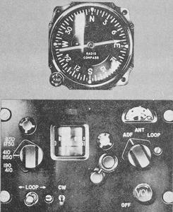 |
Figure 7-28. Modern ADF receiver.
 |
NDB (ADF) flight procedures will be discussed in Chapter VIII, "Using the Navigation Instruments." NDB approach procedure charts are described in Chapter X, "The Federal Airways System and Controlled Airspace."