Direction finding ground facilities use a cluster of vertical antennas which feed a rotating goniometer (angle-measuring device), causing an indicator to point towards an aircraft whose signal is being received. Used directly with ASR radar to locate and direct lost aircraft, the bearing information is presented both by a pointer and by a bright straight line on the radar display, starting from the location of the DF antenna and passing through the radar target representing the transmitting aircraft. Other than a VHF transmitter, no additional airborne equipment is needed to actuate the ground equipment. VHF direction finding procedures are covered in the Airman's Information Manual.
Instrument Landing System
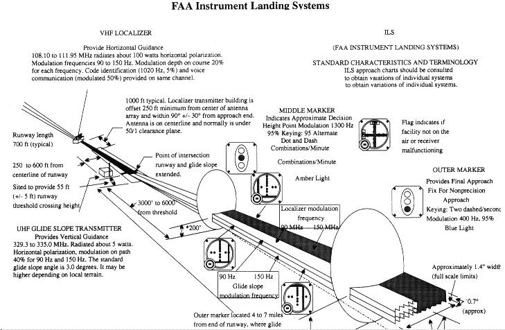
Although called an instrument landing system, the ILS (Fig. 7-29) provides a number of ground facilities, either as part of the basic system or associated with it, for several different types of instrument approaches to be discussed in a later chapter.
Ground Components
An instrument landing system consists of the following components:
1. A localizer radio course to furnish horizontal guidance to
the airport runway.
2. A glide slope radio course to furnish vertical guidance along
the correct descent angle to the proper touchdown" point on the runway.
3. Two VHF marker beacons (outer and middle) are normally installed
on the front course. They provide accurate radio fixes along the approach
path to the runway. At some locations, a third marker beacon may be employed
on the front course to indicate the point at which the decision height
should occur on a Category II ILS. A marker beacon may be installed on
the back course to indicate the back course final approach fix.
4. Approach lights are normally installed on the ILS runway
to provide means for transition from instrument to visual flight.
Figure 7-29. Instrument landing system (ILS).
|
|
The following supplementary elements, though not specific components of the system, may be incorporated into the system to increase safety and Utility.
1. Compass locators to provide transition from enroute NAVAIDs
to the ILS system; to assist in holding procedures, tracking the localizer
course, identifying the marker beacon sites; and to provide a final approach
fix for ADF approaches.
2. Distance measuring equipment (DME) co-located with the glide
slope transmitter to provide positive distance-to-touchdown information.
3. Supplementary lighting systems to facilitate transition from
instrument to outside visual references during the final stage of the approach.
Localizer
The localizer antenna array is located on the extended centerline of the instrument runway of an airport, remote enough from the opposite approach end of the runway to prevent the array from being a collision hazard.
This unit radiates a field pattern which develops a course down the centerline of the runway toward the middle and outer markers, and a similar course along the runway centerline in the opposite direction. These courses are called the "front" and "back" courses, respectively. The localizer provides course guidance throughout the descent path to the runway threshold from a distance of 18 nautical miles from the antenna between an altitude of 1,000 feet above the highest terrain along the course line and 4,500 feet above the elevation of the antenna site.
The radiated field pattern is modulated at two different frequencies. The right side of this pattern, looking along the normal approach path from the outer marker toward the runway, is modulated at 150 Hz. The left side of the radiated pattern is modulated at 90 Hz. The on-course path is formed by equi-signal points between the two modulated sides of the pattern, and becomes increasingly narrow as the transmitter is approached.
The localizer course width is defined as the angular displacement at any point along the course between a full "fly-left" and a full "fly-right" indication on the aircraft course deviation indicator (CDI or localizer needle). The localizer signal is adjusted to produce an angular width between 3° and 6°, as necessary, to provide a linear width of approximately 700 feet at the runway approach threshold. In addition, the FAA localizer provides a full "fly-left" or full "fly-right" to an aircraft well outside the on-course area, preventing the possibility of a "false course."
ILS Identification. Each localizer facility is identified by a 3-letter coded designator transmitted at frequent regular intervals. The identification is always preceded by the coded letter "I" to identify the received signal as originating at the ILS facility. For example, the ILS localizer at Springfield, Mo., transmits the identifier "ISGF." The localizer includes a voice feature on its frequency for use by the associated Air Traffic Control facility in issuing approach and landing instructions. The frequency band of the localizer equipment is 108.10 to 111.95 MHz.
Glide Slope
The term "glide slope" means the complete radiation pattern generated by the glide slope facility. The term "glide path" means that portion of the glide slope that intersects the localizer. The glide slope equipment is housed in a building approximately 750 to 1,250 feet from the approach end of the runway, between 400 and 600 feet to one side of the centerline. The course projected by the glide slope equipment is essentially the same as would be generated by a localizer operating on its side, with the upper side of the course modulated at 90 Hz and the lower side at 150 Hz. The glide slope projection angle is normally adjusted to 2.5 to 3 degrees above horizontal so that it intersects the middle marker at about 200 feet and the outer marker at about 1,400 feet above the runway elevation. At locations where standard minimum obstruction clearance cannot be obtained with the normal maximum glide slope angle, the glide slope equipment is displaced inward from the standard location if the length of the runway permits.
Unlike the localizer, the glide slope transmitter radiates signals only in the direction of the final approach on the "front course." The system provides no vertical guidance for approaches on the "back course." The glide path is normally 1.4° thick. At 10 nautical miles from the point of touchdown, this represents a vertical distance of approximately 1,500 feet, narrowing to a few feet at touchdown.
False Courses. In addition to the desired course, glide slope facilities inherently produce additional courses at higher vertical angles; the angle of the lowest of these "false courses" will occur at approximately 12.5. However, if your approach is conducted at the altitudes specified on the appropriate approach chart, these false courses will not be encountered.
Marker Beacons
Two VHF marker beacons, outer and middle, are normally used in the FAA ILS system. A third beacon, the inner, is used where Category II operations are certified. Also, a marker beacon may be installed to indicate the final approach fix on the ILS back course.
These beacons have a power output of 3 watts or less and operate on a frequency of 75 MHz. The radiation patterns are fan-shaped with an elliptical cross-section with its minor axis parallel to the approach path and its major axis at right angles to the approach path.
The Outer Marker (OM) is located on the front course 4 to 7 miles
from the airport and indicates a position at which an aircraft, at the
appropriate altitude on the localizer course, will intercept the glide
path. The outer marker is modulated at 400 Hz. It is identified by continuous
dashes at the rate of 2 per second, and a purple marker beacon light.
The Middle Marker (MM) is located approximately 3,500 feet from
the landing threshold on the centerline of the localizer front course.
The middle marker is modulated at 1300 Hz. It is identified by alternate
dots and dashes at the rate of 95 dot/dash combinations per minute, and
an amber marker beacon light.
The Inner Marker (IM), where installed, is located on the front course between the middle marker and the landing threshold. It indicates the point at which an aircraft is at the decision height on the glide path during a Category II ILS approach. The inner marker is modulated at 3000 Hz. It is identified by continuous dots at the rate of 6 per second, and a white marker beacon light.
The Back Course Marker (BCM), where installed, indicates the back course final approach fix. The back course marker is modulated at 3000 Hz and identified with 2 dots at a rate of 72 to 75 2-dot combinations per minute, and a white marker beacon light.
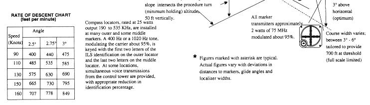
Compass Locators. Compass Locators are low powered nondirectional radio beacons which operate between 200 and 415 kHz. When used in conjunction with an ILS front course, the compass locator facilities are co-located with the Outer and Middle Marker facilities (shown as LOM and LMM on instrument approach charts). The coding identification of the Outer Locator consists of the first two letters of the station identifier; for example, the Outer Locator at Love Field, Dallas, Tex., (DAL) is identified as "DA." The Middle Locator at DAL is identified by the last two letters "AL."
Approach Lighting Systems
Normal approach and letdown on the ILS is divided into two distinct stages: the "instrument" approach using only radio guidance, and the "visual" stage, when visual contact with the ground is necessary for accuracy and safety. The most critical period of an instrument approach, particularly during low ceiling/visibility conditions, is at the point when you must decide whether to land or execute a missed approach.
The purpose of the approach lighting system is to provide you
with lights that will penetrate the atmosphere far enough from touchdown
to give you directional, distance, and glide path information for safe
visual transition. Checking the Airport/ Facility Directory for the particular
type of lighting facilities at your destination airport is an important
flight planning detail for any instrument flight. With reduced visibility,
rapid orientation to a strange runway can be difficult, especially during
a circling approach to an airport with minimum lighting facilities, or
to a large terminal airport located in the midst of distracting lights.
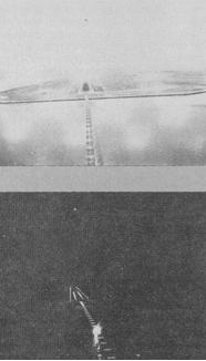
The approach lighting system shown in Figure 7-30 is a common
installation as you would see it when properly aligned from the runway
end. The same approach lighting system in Figure 7-30 is a common installation
as you would see it when properly aligned from the runway end. The same
approach is illustrated under day and night conditions.
Figure 7-30. Approach light system.
 |
A high-intensity flasher system is installed at many large airports.
The flashers consist of a series of very brilliant blue-white bursts of
light flashing in sequence along the approach lights giving the effect
of a ball of light traveling towards the runway.
Runway End Identifier Lights (REIL) are installed for rapid and
positive identification of the approach end of an instrument runway. The
system consists of a pair of synchronized flashing lights, one of which
is located laterally on each side of the runway threshold facing the approach
area.
The Visual Approach Slope Indicator (VASI) gives visual descent guidance information during the approach to a runway. The standard VASI consists of light bars that project a visual glide path which provides safe obstruction clearance within the approach zone. The normal glide slope angle is 3°; however, the angle may be as high as 4.5° for proper obstacle clearance. On runways served by ILS, the VASI angle normally coincides with the electronic glide slope angle. Course guidance is obtained by alignment with the runway lights.
The standard VASI installation consists of either 2-, 4-, 6-, 12-, or 16-light units arranged in downwind and upwind light bars. Some airports serving longbodied aircraft have 3-bar VASIs which provide two visual glide paths to the same runway. The first glide path encountered is the same as provided by the standard FAA VASI. The second glide path is about 1/4° higher than the first and is designed for the use of pilots of long-bodied aircraft.
The basic principle of VASI is that of color differentiation be tween red and white. Each light projects a beam having a white segment in the upper part and a red segment in the lower part. The light units of a standard FAA 2-bar VASI are arranged so you will see them as illustrated in Figure 7-31.
From a position above the glide path you will see both bars as white. Moving down the glide path, you will see the color of the upwind bars change from white to pink to red. When you are on the proper glide path, you will overshoot the downwind bars and undershoot the upwind bars. Thus you will see the downwind bars as white and the upwind bars as red. From a position below the glide path you will see both light bars as red. Moving up to the glide path, you will see the color of the downwind bars change from red to pink to white. When below the glide path, as indicated by a distinct red signal, a safe obstruction clearance may not exist.
As you approach the runway threshold, the visual glide path will separate into individual lights. At this point, you should continue the approach by reference to the runway touchdown zone.