For reception of electronic signals from all of the ILS transmitting
facilities described, your airborne equipment will include the following
receivers:
1. Localizer receiver.
2. Glide slope receiver.
3. Marker beacon receiver.
4. ADF receiver.
5. DME receiver.
Use of the ILS does not require all of these components, however. For example, an instrument approach on the ILS system may be made with only localizer and marker beacon receivers (sometimes called a "localizer approach"); with only localizer and ADF receivers; or with an ADF receiver only, using the locator as a primary approach aid. The authorized landing minimums will of course vary according to the ground and airborne equipment available and operating properly.
Localizer Receiver. The typical light-plane VOR receiver is also a localizer receiver with common tuning and indicating equipment. Some receivers have separate function selector switches. Otherwise, tuning of VOR and localizer frequencies is accomplished with the same knobs and switches, and the CDI indicates "on course" as it does on a VOR radial.
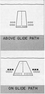
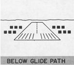
Figure 7-31. Standard FAA 2-bar VASI.
|
|
|
Glide Slope Receiver. Though some glide slope receivers are tuned separately, in a typical installation the glide slope is tuned automatically to the proper frequency when the localizer is tuned in. Each of the 40 localizer channels in the 108.10 to 111.95 MHz band is paired with a corresponding glide slope frequency of the 40 UHF glide slope channels available (see AIM). Although all of these 40 frequency pairs are not presently being utilized, they will be in the future.
Localizer/Glide Slope Indicator. When the localizer indicator also includes a glide-slope needle, the instrument is often called a crosspointer indicator. The crossed horizontal (glide-slope) and vertical (localizer) needles are free to move through standard 5-dot deflections to indicate position on the localizer course and glide path. See Figure 7-32.
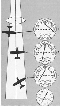
The localizer needle indicates, by deflection, whether the aircraft is right or left of the localizer centerline, regardless of the position or heading of the aircraft. Rotation of the omni bearing selector has no effect on the operation of the localizer needle. When the aircraft is inbound on the front course or outbound on the back course, the needle is deflected toward the on-course (A, Fig. 7-33) and you turn toward the needle to correct your track. Conversely, when the aircraft is inbound on the back course or outbound on the front course, you turn away from the direction of needle deflection to reach the center of the localizer course (B, Fig. 7-33). With an ADF tuned to the outer compass locator, orientation on the localizer course is simplified (C, Fig. 7-33). The problem of orientation with respect to both the localizer course and VOR radials will be discussed in Chapter VIII, "Using the Navigation Instruments."
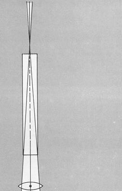
The localizer course is very narrow, normally 5°. This results in high needle sensitivity. With this course width, a full-scale deflection shows when the aircraft is 2.5° to either side of the centerline. This sensitivity permits accurate orientation to the landing runway. With no more than 1/4-scale deflection maintained, your aircraft will be aligned with the runway. High needle sensitivity also tends to encourage overcontrolling, until you learn to apply correct basic flying techniques for smooth control of the aircraft.
Deflection of the glide slope needle indicates the position of the aircraft with respect to the glide path (Fig. 7-34). When the aircraft is above the glide path, the needle is deflected downward. When the aircraft is below the glide path, the needle is deflected upward.
When the aircraft is on the glide path, the needle is horizontal, overlying the reference dots. Since the glide path is much sharper than the localizer course (approximately 1.4° from full "up" to full down" deflection), the needle is very sensitive to displacement of the aircraft from on-path alignment. With the proper rate of descent established on glide slope interception, very small corrections keep the aircraft aligned.
The localizer and glide slope warning flags disappear from view on the indicator when sufficient voltage is received to actuate the needles. The flags show when an unstable signal or receiver malfunction occurs.
ILS flight procedures will be discussed in Chapter VIII, "Using the Navigation Instruments." ILS approach procedure charts are described in Chapter X, "The Federal Airways System and Controlled Airspace." Additional information on the FAA ILS system appears In the Airman's Information Manual under the heading, AIR NAVIGATION RADIO AIDS.
Figure 7-32. Localizer-glide slope indicator.
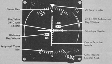 |
Figure 7-33. Localizer receiver indications.
 |
|
 |