You will be concerned in this section with the forces affecting aircraft performance caused by the interaction of air and the aircraft. With an understanding of these forces, you will have a sound basis for predicting how the aircraft will respond to your control. Important as these forces are to the VFR pilot, they must be even more thoroughly understood by the student of instrument flying. You will find, as you learn the basic instrument flying maneuvers, that your understanding of why the aircraft reacts in a particular way to your control is the key to your interpretation of information shown on the instrument panel. The importance of these aerodynamic forces and their direct application to your execution of aircraft maneuvers will be evident. Several basic aerodynamic definitions apply to a discussion of these forces.
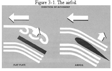
If a flat plate is moved through the air (Fig. 3-1), the airstream which strikes the plate is forced downward on impact against the plate. The reaction to this downward force produces a resultant force upward (lift) and a backward force (drag). A rock or a barn door will fly, given an airstream sufficient to produce lift. More efficient is the airfoil, a surface constructed to produce the maximum lift with the minimum drag. Airfoil shapes vary according to the aircraft performance to which the airfoil is designed. The most efficient shape, for the type of aircraft used for civilian instrument training, has a rounded leading edge, smooth cambered surfaces, and a sharp trailing edge.
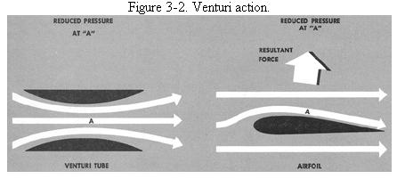
As the wing moves through the air, the airstream is divided, part
of it flowing over one surface while the remainder flows under the other
surface (Fig. 3-2). The air flowing over the upper cambered surface, as
shown in the diagram, has a longer path to travel and has to flow faster
than the air over the opposite surface to reach the trailing edge at the
same time. Application of Bernoulli's principle to both Venturi tube and
airfoil shows that the air flowing faster exerts the lesser pressure. Because
of the resulting differential pressure, the wing is supported by the higher
pressure below the lower surface.
|
 |
Lift is also produced at the leading edge when it is so designed that the approaching airstream divides near the lower part of the airfoil.
The trailing edge of the wing is also designed for efficient airflow. If the trailing edge were rounded, the lower stream of air would tend to curve around into the area of lower pressure along the upper surface, introducing undesirable forces opposing lift on the after part of the airfoil. A sharp trailing edge permits smooth flow of the upper and lower airstreams past the trailing edge.
The lift/drag characteristics which are determined by airfoil design are affected by other basic factors related to control of aircraft performance.
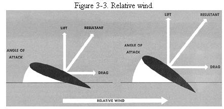
The relative wind (Fig. 3-3) is the motion of the air relative to the chord line of the airfoil. The air can be moving past the airfoil or the airfoil can be moving through the air. The relative wind, as applied to airplanes, is parallel and opposite to the flight path of the aircraft.
The angle of attack is the acute angle measured between the chord line of the wing and the relative wind - not between the chord line and the Earth's surface. The chord line of an airfoil is merely a conveniently chosen reference line in the wing to measure the real or theoretical width of the wing.
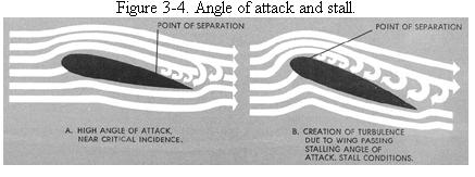
A stall is the result of any condition that disrupts the smooth
flow of air over the airfoil to the point where sufficient lift is no longer
produced by the differential pressure. The wing can stall in any attitude
and at any speed. As the angle of attack of the wing is increased, the
air particles are forced to make sharper and sharper changes in direction
to follow the contour of the wing. With increasing angles of attack, disruption
of smooth airflow occurs initially at the trailing edge and moves forward
toward the leading edge at higher angles of attack. The wing stalls when
the progressive increase in turbulence on the top cambered surface results
in a net loss of lift (Fig. 3-4).
 |
 |
Aerodynamic Forces
Lift always acts in a direction perpendicular to the relative wind and to the lateral axis of the aircraft. The fact that lift is referenced to the wing, not to the Earth's surface, is the source of many errors in learning flight control. Lift is not always "up." Its direction relative to the Earth's surface changes as you maneuver the aircraft. The magnitude of the force of lift is directly proportional to the density of the air, the area of the wings, and the airspeed. It also depends upon the type of wing and the angle of attack. Lift increases with an increase in angle of attack up to the stalling angle, at which point it decreases with any further increase in angle of attack. In conventional aircraft, lift is therefore controlled by varying angle of attack (attitude) and thrust.
Drag is the total resistance of the air to the movement of the aircraft. Drag acts opposite to the direction of flight of the aircraft and is parallel to the relative wind. Induced drag is the result of the same inherent aerodynamic forces that produce lift. Parasite drag is the resistance to airflow caused by inefficient streamlining, skin friction, and projections into the airstream. Total drag is the sum of induced and parasite drag and is affected by airspeed and air density as well as the other factors noted. Changes in drag, whether induced during attitude changes or the result of gear and/or flap extensions, are reflected in performance changes indicated on your flight instruments.
Thrust in conventional propeller-driven aircraft is the force acting forward with respect to the longitudinal axis of the aircraft. The amount of thrust is determined by the power output of the engine, and for all practical purposes acts parallel to the longitudinal axis. Use of power controls thrust, and therefore lift and performance.
Weight is the force of gravity acting on the aircraft and is always downward toward the center of the Earth regardless of aircraft attitude and flight path. Both the total weight and its distribution affect aircraft flight characteristics. The relationship of these fundamental factors to aircraft performance in various basic flight attitudes and conditions must be understood if you are to control your aircraft with precision.
Straight-and-Level Flight
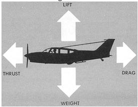
Straight-and-level flight is a performance term meaning that an aircraft is maintaining a constant indicated altitude and a constant heading. In coordinated, unaccelerated, straight-and-level flight, weight acts downward toward the center of the Earth; lift acts perpendicular to the relative wind and is equal and opposite to weight; drag acts parallel to the relative wind; and thrust acts forward, parallel to the longitudinal axis, and equal and opposite to drag.
In coordinated, straight-and-level, unaccelerated flight, all opposing forces are balanced (Fig. 3-5), and as long as the specific flight attitude and thrust are maintained, altitude and heading remain constant. Any variation in these forces requires a different attitude (relationship of the aircraft's longitudinal and lateral axes with the Earth's surface) if the aircraft is to maintain level flight.
Figure 3-5. Forces in straight-and-level unaccelerated flight.
 |
Three factors affect attitude in maintaining level flight - airspeed, air density, and aircraft weight.
(1) Airspeed. At a constant angle of attack, any change in airspeed will vary the lift. At low airspeeds, the angle of attack must be proportionately greater to produce the lift necessary for level flight. The aircraft must therefore be flown in a nose-high attitude to maintain level flight at low speeds. At progressively higher airspeeds, the angle of attack necessary to produce sufficient lift for level flight becomes smaller, and the nose of the aircraft is accordingly lowered. Assuming that weight remains constant, any specific airspeed in unaccelerated level flight is associated with a specific thrust and attitude. In other words, if more power is applied than required for level flight, the aircraft will accelerate if held level, or climb if airspeed is held constant.
(2) Air Density. Lift varies directly with changes in air density,
which decreases as either altitude, air temperature, or humidity increases.
Thus, to maintain level flight at a given true airspeed, the angle of attack
of an airfoil must be greater at higher altitudes and/or outside air temperatures
than at lower altitudes and/or temperatures. To maintain level flight at
high "density altitudes," the aircraft attitude must be relatively nose-high.
(3) Aircraft Weight. For a given weight and airspeed, a specific
angle of attack is required to maintain straight-and-level flight. To support
heavier loads at a given airspeed, the angle of attack must be relatively
greater to provide the necessary lift. To overcome the induced drag resulting
from the increased angle of attack, more thrust is also needed to maintain
the given airspeed.
Climbs
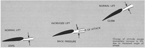
For all practical purposes, the lift in normal climbs is the same as in level flight at the same airspeed. Though the flight path has changed, the angle of attack of the wing with respect to the flight path remains the same, as does the lift. There is a momentary change however, as shown in Figure 3-6. In going from straight-and-level flight to a climb, a change in lift occurs when back elevator pressure is applied. Raising the nose increases the angle of attack and momentarily increases the lift. Lift, now greater than weight, causes the aircraft to climb. The flight path is inclined upward, and the angle of attack and lift again stabilize.
If the climb is entered without a change in power setting, the airspeed gradually diminishes because the thrust required to maintain a given airspeed in level flight is insufficient to maintain the same airspeed in a climb. Due to momentum, the change in airspeed is gradual, varying considerably with differences in aircraft size, weight, total drag, and other factors. As the angle of attack changes, a component of the weight acts in the same direction, and parallel to, the total drag of the aircraft, thereby increasing the total drag and decreasing the airspeed. The reduction in airspeed results in a corresponding decrease in drag until the total drag (including the component of weight acting in the same direction) equals the thrust.
The forces are again balanced when the airspeed stabilizes at a value lower than in straight-and-level flight at the same power setting. Lift is equal in magnitude to the component of weight that is perpendicular to the flight path. In a climb, this perpendicular weight component is only part of the weight, the other component acting to increase the total drag. Because the latter component must be balanced by thrust, you must increase thrust (power) to maintain constant airspeed on entering a climb from level flight, the amount of power depending on the change in angle of attack.
Descents
On entering a normal descent from straight-and-level flight without a change in power, a disturbance in balanced forces likewise occurs. As a result of forward pressure on the elevator controls, the angle of attack is reduced and the lift proportionately reduced. The weight being greater than the lift, the aircraft follows a descending flight path. A component of the weight now acts forward along the flight path parallel to the thrust, causing a gradual increase in airspeed as well as an increase in drag. When the angle of attack stabilizes and the lift/weight and thrust/drag forces again balance, the aircraft descends at a constant airspeed. Therefore, to enter a descent from level flight, maintaining a constant airspeed, you must decrease power to prevent an increase in thrust resulting from the forward alignment of the weight component.
Power, Airspeed, and Vertical Speed
In a descent, the component of weight acting forward along the flight path increases as the angle of descent increases and decreases as the angle of descent decreases. The power reduction required to maintain a given airspeed in the descent, depends on the rate of descent desired. For example, a high rate of descent at a specific airspeed, requires a greater power reduction than does a lower rate of descent. The proper combination of pitch attitudes, airspeeds, vertical velocities, and power settings for climbs and descents must be learned for each individual aircraft. Having learned the principles and techniques for the execution of these maneuvers for one aircraft, you can readily apply them to other aircraft.
Figure 3-6. Climb entry.
 |
Power, Airspeed, and Elevator Control
Rotating the aircraft about the lateral axis is accomplished by forward or aft movement of the elevator control to displace the elevators. The use of the elevators varies with changes in power and airspeed. The slip stream striking the elevators in a downward direction creates a negative angle of attack for the elevators and causes them to exert a negative lift. Changes in power and airspeed vary the amount of downwash and the resulting negative lift exerted by the elevators. As power and airspeed increase, slipstream velocity and downwash lift on the elevators increases. At the same time, lift on the wing increases and the aircraft has a nose-high tendency. Therefore, if the aircraft is trimmed for level flight, an increase in power and airspeed must be accompanied by forward pressure on the controls if you are to remain in level flight.
A decrease in power and/or airspeed has the opposite effect. The negative lift on the elevators and the lift on the wing decrease, resulting in a nose-low tendency. As you reduce power and/or airspeed, you must hold back pressure on the controls to maintain level flight.
Trim
In the simplest terms, trim may be thought of as balance, which is affected by design, loading, atmospheric conditions, and the aerodynamic factors already considered. Aircraft are designed so that weight always acts through a point called the center of gravity, located along the longitudinal axis at some point within specified limits behind the leading edge of the wing. Likewise, lift acts through a point called the center of pressure, located aft of the center of gravity. Since these two points do not coincide, lift and weight exert a twisting force resulting in a normal nose-heaviness. The twisting force is balanced by the negative lift produced by the horizontal stabilizer and elevators. However, as shown earlier, elevator control and the negative lift of the elevators vary with power/airspeed changes, requiring control application as the balanced forces are disturbed. Aircraft balance is affected not only by design and performance factors, but also by the shifting of the center of gravity and the center of pressure in flight, by the rigging of the aircraft, and by the action of torque and P-factor effects in propeller-driven aircraft.
With the application of power in propeller driven aircraft, torque yaws the nose of the aircraft to the left. This yaw is controlled by the rudder, and the effectiveness of the rudder depends upon the amount of rudder displacement and the airflow. The airflow depends upon the airspeed and slip-stream velocity. Consequently, the nose will also tend to yaw to the left if airspeed is reduced while the power remains constant. Torque control thus depends upon airspeed, technique in the application or reduction of power, and the amount of torque inducing the yaw.
All of the above factors affecting changes in aircraft balance can be counteracted in light aircraft without the use of trim controls. In fact, many pilots commonly neglect proper trim technique and maintain continual control pressures to hold the aircraft in the desired stabilized attitude. This is not only fatiguing, but undesirable for additional reasons to be considered later. Trim devices vary in different aircraft.
In the simplest light aircraft, only an elevator trim control is provided. If such aircraft are used for instrument training, yawing or rolling tendencies must be counteracted by holding aileron and/or rudder pressures to maintain the desired aircraft attitude. With increased aircraft performance, rudder and elevator trim controls are essential, and in high performance or transport-type aircraft, aileron trim control is also necessary. In many light aircraft having no aileron trim control, the left/right fuel selector has a trim function. Wing heaviness on either side, requiring aileron control to maintain attitude, can be corrected by fuel consumption from the heavy side.
Turns
Many of the common misconceptions associated with aircraft performance and pilot control techniques are traceable to ignorance of aerodynamic forces and their varying effects as the aircraft is maneuvered. Our thinking and terminology are oriented to the ground rather than to the air, and these contribute to misunderstandings. For example, we think of "up" and "down" as referenced vertically to the Earth's surface, and the elevators (also a ground-referenced term) as the means of up/down control. Back elevator control pressure should mean "up," and forward elevator, "down." This is true to varying degrees and under certain flight conditions. Under other conditions, back elevator control pressure will fail to produce any "up" result. A related misconception is that because weight always acts downward, lift always acts upward and opposite to weight. This is not always so.
Another mistaken notion is that an aircraft is turned by the rudder(s). This is understandable since the term "rudder" implies a turning function. Further, since the rudder controls rotation about the vertical axis, does it not follow that the aircraft is turned by rudder action? True, you can turn an aircraft by moving the rudder. You can also bank the aircraft, or move the nose up, by rudder control, just as you can raise or lower the nose by power changes. Because of these effects of control application, misconceptions understandably arise as to the proper function of the controls. The fact that the rudder is normally used in turning a conventional aircraft, or that the throttle is used in the execution of climbs and descents simply means that yaw must be controlled in a properly executed turn, and that thrust must be controlled to climb or descend under specified conditions. The interrelated functions of the controls will be clearer as you study the aerodynamics of a turn.
Forces Acting on an Aircraft in Turns
An aircraft, like any moving object, requires a sideward force to make it turn. In a normal turn, this force is supplied by banking the aircraft so that lift is exerted inward as well as upward. The force of lift is thus separated into two components at right angles to each other (Fig. 3-7). The lift acting upward and opposing weight is called the vertical lift component. The lift acting horizontally and opposing centrifugal force is called the horizontal lift component. The horizontal lift component is the sideward force that causes an aircraft to turn. The equal and opposite reaction to this sideward force is centrifugal force. If an aircraft is not banked, no force is provided to make it turn unless the turn is skidded by rudder application. Likewise, if an aircraft is banked, it will turn unless held on a constant heading in a slip. Proper instrument interpretation and aircraft control technique assumes that an aircraft is turned by banking, and that in a banking attitude it should be turning.
Changes in Lift in a Turn
Banking of an aircraft in a level turn does not by itself produce a change in the amount of lift. However, the division of lift into horizontal and vertical components reduces the amount of lift supporting the weight of the aircraft. Consequently, the reduced vertical component results in the loss of altitude unless the total lift is increased by (1) increasing the angle of attack of the wing, (2) increasing the airspeed, or (3) increasing the angle of attack and airspeed in combination. Assuming a level turn with no change in thrust, you increase the angle of attack by raising the nose until the vertical component of lift is equal to the weight. The greater the angle of bank, the weaker is the vertical lift component, and the greater is the angle of attack for the lift/weight balance necessary to maintain a level turn.
Angle of Bank and Rate of Turn
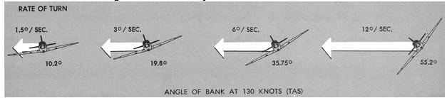
The rate of turn at any given airspeed depends on the amount of sideward force causing the turn; that is, the horizontal lift component. The horizontal lift component varies directly in proportion to bank in a correctly executed turn. Thus, the rate of turn at a given airspeed increases as the angle of bank increases (Fig. 3-8). As the illustration shows, at 130 knots and approximately 10° of bank, an aircraft completes a 360° turn in 4 minutes. At the same airspeed and approximately 55° of bank, the rate of turn is eight times as great.
Figure 3-7. Lift components.
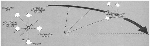 |
Figure 3-8. Relationship between bank and rate of turn.
 |
Drag Factors in Turns
Drag is induced both by changes in angle of attack and by displacement of the ailerons as the aircraft rolls into, or out of, a turn. As you raise the nose of the aircraft to increase the lift in a level turn, the drag increases directly in proportion to the increase in angle of attack. The resulting decrease in airspeed is, therefore, proportional to the angle of bank. If you wish to maintain constant airspeed in a level turn, you must add power in proportion to the angle of bank used.
If the ailerons alone are used to roll into a turn, the aircraft will tend to yaw in the direction opposite to the direction of turn, the amount of yaw depending upon the amount of aileron displacement and smoothness or abruptness of control technique.
Deflection of ailerons increases the lift on the outside wing and decreases the lift on the inside wing. The drag is proportionately increased on the outside wing, resulting in the yawing effect known as "aileron drag" or "adverse yaw." The function of the rudder in a correctly executed entry and recovery from a turn is to counteract this aileron drag. Once the desired bank angle is established and the ailerons are streamlined, no aileron drag exists and the need for rudder control ceases.
Constant Rate Turns
If the airspeed is increased in a turn, the angle of attack must be decreased and/or the angle of bank increased in order to maintain level flight.
As airspeed is increased in a constant-rate level turn, both the radius of turn and centrifugal force increase. This increase in centrifugal force must be balanced by an increase in the horizontal lift component, which can be accomplished only by increasing the angle of bank. Thus, to maintain a turn at a constant rate, the angle of bank must be varied with changes in airspeed (Fig. 3-9).
Load Factors and Angle of Bank
A load factor is the ratio of a specified load to the total weight of the airplane. The specified load may be expected in terms of aerodynamic forces, as in turns. In level flight in undisturbed air, the load factor is 1; the wings are supporting only the weight of the airplane. In a coordinated level turn, the wings are supporting not only the weight of the aircraft, but centrifugal force as well. As the bank steepens, the horizontal lift component increases, centrifugal force increases, and the load factor increases (Fig. 3-10). In a coordinated level turn with a 60° bank, the wings support a load equal to twice the weight of the aircraft. To provide the lift to balance this load, the angle of attack must be increased. However, if the load factor becomes so great that an increase in angle of attack cannot provide enough lift to support the load, the wing stalls. Since the stalling speed increases directly with the square root of the load factor, you should be aware of the flight conditions during which the load factor can become critical. Steep turns at low airspeed, structural ice accumulation, and vertical gusts in turbulent air can increase the load factor to a critical level.
Slips and Skids
In straight-and-level, unaccelerated flight, an aircraft points directly along its flight path, except when it is slipping or skidding (Fig. 3-11).
The aircraft may be yawed toward either side of the flight path by rudder action or by incorrect adjustment of the rudder trim tab. The same yawing effect can be caused by inaccurate aileron rigging. If one aileron is deflected slightly downward and the other is aligned properly, the aircraft will tend to yaw in the direction of the down aileron. If the aircraft is in proper trim, with the forces in equilibrium around its pitch, roll, and yaw axes, stabilizing forces will act to maintain this equilibrium. Following a slip or skid, if the aircraft is trimmed for straight-and-level flight and no control forces are held against this stabilizing tendency, the act of the relative wind against the vertical surfaces will restore the aircraft to proper alignment with the flight path.
Figure 3-9. Sensations from centrifugal force.
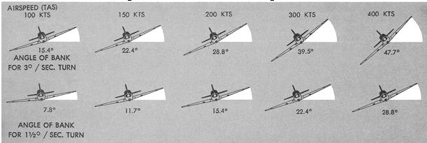 |
Figure 3-10. Relation of load factor to bank.
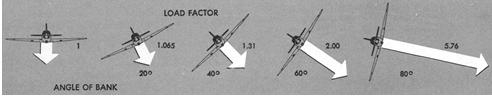 |
Figure 3-11. Forces during normal, slipping, and skidding turns.
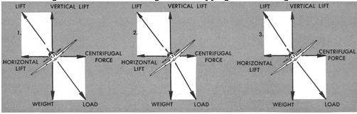 |
1. Normal turn. 2. Slipping turn. 3. Skidding turn.
Centrifugal force equals Centrifugal force less than
Centrifugal force greater than
horizontal lift. horizontal lift. horizontal lift.
To maintain straight flight in propeller-driven aircraft without slipping or skidding, rudder trim must be adjusted following changes in power settings and/or airspeed because the changes in torque effect and the airstream over the vertical tail surfaces varies the directional control. In aircraft having no controllable rudder trim, rudder pressure must be held to maintain directional trim during changes of power and/or airspeed.
Slips.
During a controlled slip, the aircraft is banked, and as noted earlier, the banking normally results in a turn. By application of rudder control opposite the direction of bank, the aircraft is prevented from turning. The banking results in sideways movement of the aircraft with respect to the direction maintained by rudder control.
In a slipping turn - level, climbing, or descending - the aircraft is not turning at the rate appropriate to the bank being used and the aircraft is yawed toward the outside of the turning flight path. The aircraft is banked too much for the rate of turn, so the horizontal lift component is greater than the centrifugal force. Thus, the ball of the turn-and-slip indicator is displaced in the direction of bank, toward the inside of the turn. Equilibrium between the horizontal lift component and centrifugal force is reestablished either by decreasing the bank, increasing the rate of turn, or a combination of the two changes.
Skids.
A skid occurs in straight-and-level flight when the aircraft yaws either to the right or left, out of alignment with the desired flight path. A skidding turn results from excess of centrifugal force over the horizontal lift component, pulling the aircraft toward the outside of the turn. The rate of turn is too great for the angle of bank, and the ball in the turn-and-slip indicator is displaced toward the outside of the turn. Correction of a skidding turn thus involves a reduction in the rate of turn, an increase in bank, or a combination of the two changes.
Coordination of Rudder and Aileron Controls
Coordination has a very specific meaning as applied to instrument flight techniques. It means using the controls to maintain or establish various conditions of flight with (1) a minimum disturbance of the forces maintaining equilibrium, or (2) the control action necessary to effect the smoothest changes in equilibrium. A controlled slip or skid, for example, requires considerable muscular coordination; the resulting slip or skid, however, is not a coordinated maneuver in the aerodynamic sense.
Coordination of controls during flight by reference to instruments requires that the ball of the turn-and-slip indicator be kept centered, and that available trim control devices be used whenever a change in flight condition disturbs the existing trim. Development of coordinated control technique depends not only on your understanding of the foregoing aerodynamic considerations, but on your attention to the characteristics of the particular type of aircraft in which you train.
Control sensitivities vary considerably in different aircraft and in a given aircraft at various speeds. From experience, you learn that one aircraft is extremely sensitive on rudder control and perhaps noticeably resistant to the movement of elevator control; another aircraft has less than normal lateral stability and tends to overbank; another responds to thrust and drag changes unlike other aircraft. Your application of control pressures must be adapted to each airplane you fly.
Knowing why the aircraft will respond to your control will accelerate your progress in acquiring competent instrument flying techniques.