Tracking, in contrast to homing, involves drift correction sufficient to maintain a direct course to or from a transmitting station. The course selected for tracking inbound is the course shown under the course index with the TO/FROM indicator showing "TO". If you are off course to the left, the CDI is deflected right; if you are off course to the right, the CDI is deflected to the left. Turning toward the needle returns the aircraft to the course centerline and centers the needle.
To track inbound with the wind unknown, proceed in the following steps (Fig. 8-5). Outbound tracking procedures are the same.
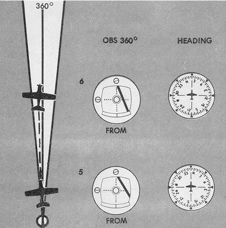
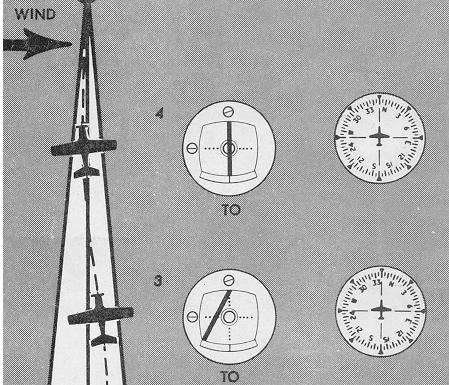
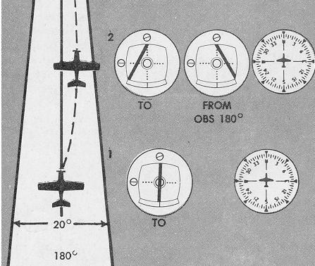
Figure 8-5. VOR tracking.
|
|
|
|
|
1. With the CDI centered, maintain the heading corresponding
to the selected course.
2. As you hold the heading, observe the CDI for deflection to
left or right. Direction of CDI deflection from centerline shows the direction
of the crosswind component. The illustration shows a left deflection, therefore
left crosswind.
(Note the indications with the reciprocal of the inbound course
set on the OBS. The indicator correctly shows "FROM", and the aircraft
to the left of the centerline with reference to the selected course. Sometimes
called "reverse sensing" this CDI deflection indicates a turn away from
the needle for direct return to the course centerline, and illustrates
the importance of correlating heading and course selection. VOR tracking
can be accomplished with "reverse sensing," but errors in orientation can
easily result.)
3. Turn 20° toward the needle and hold the heading correction
until the needle centers.
4. Reduce the drift correction to 10° left of the course
setting, and note whether this drift-correction angle keeps the CDI centered.
Subsequent left or right needle deflection indicates an excessive or insufficient
drift-correction angle, requiring further bracketing. With the proper drift-correction
angle established, the CDI will remain centered until the aircraft is close
to the station. Approach to the station is indicated by flickering of the
TO/FROM indicator and CDI as the aircraft flies into the "cone of confusion"
(no-signal area). Station passage is shown by complete reversal of the
TO/FROM indicator. The extent of the cone of confusion, an inverted cone,
increases with altitude. Thus, flight through the cone of confusion varies
from a few seconds at low levels to as much as 2 minutes at high altitude.
5 and 6. Following station passage and TO/FROM reversal, correction
to course centerline is still toward the needle. Note that the extent of
CDI deflection is, by itself, no indication of the amount of aircraft displacement
from the course centerline. A large CDI deflection immediately following
station passage calls for no heading correction until the CDI stabilizes;
at 20 miles out, a two-dot deflection may require a large correction angle
for return to centerline.
The rate of movement of the CDI during course bracketing is thus
an approximate index of distance from the station. For accurate radial
interception and course following, the data given in Figure 8-6 may be
helpful.
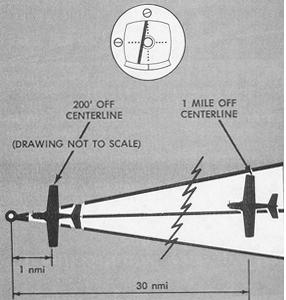
Assuming a receiver with normal course sensitivity and full-scale
deflection at 5 dots:
Aircraft displacement from course is approximately 200 ft. per
dot per nautical mile. For example, at 30 nautical miles from the station,
one dot deflection indicates approximately one nmi displacement of the
aircraft from the course centerline.
Time/Distance Checks by VOR. Time and distance from a VOR station
can be determined by several methods involving practical application of
formulas or elementary geometry. These time/distance computations are approximations
since wind drift is not considered in the solutions.
Figure 8-6. CDI deflection and aircraft displacement from course.
 |
Wing-Tip Bearing Change. The formula solution is applied to the elapsed time for a predetermined change in azimuth, or relative bearing, from the aircraft to a station located at 90° from the aircraft heading (Fig. 8-7).
Figure 8-7. Time-distance check (VOR); wing-tip bearing change.
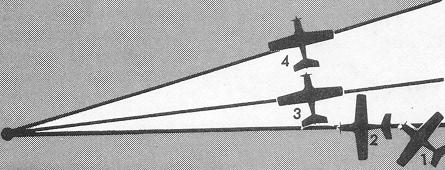 |
Determine time/distance to station by the following steps. After
tuning and identifying the VOR station:
1. Determine the radial on which you are located.
2. Turn inbound and re-center the needle if necessary.
3. Turn 80° right, or left, of the inbound course, rotating
the OBS to the nearest 10° increment opposite the direction of turn.
4. Maintain heading. When the CDI centers, note the time.
5. Maintaining the same heading, rotate the OBS 10° in the
same direction as in step 3, above.
6. Note the elapsed time when the CDI again centers.
7. Time/distance from the station is determined from the following
formulas:
60 x minutes flown between
bearing change
(a) Time to station = ----------------------------------
degrees of bearing change
TAS x minutes flown
(b) Distance to station = ------------------------------
degrees of bearing change
By analysis of the time formula, above, you can derive the following rules of thumb:
Degrees of bearing change:
Time to station
10 .............. 6 x time
(in minutes) of bearing change
5 ..............12
x time (in minutes) of bearing change
20 .............. 3 x time
(in minutes) of bearing change
Even more simply, for a 10° bearing change, note the elapsed time in seconds. One-tenth of this time is the time in minutes to the station. For example, if a 10° wing-tip bearing change takes 80 seconds, you are 8 minutes from the station. The amount of bearing change flown should vary, depending upon the distance of the aircraft from the station and groundspeed crossing radials.
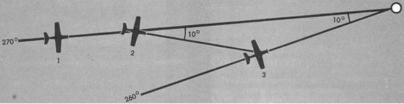
Isosceles Triangle Method (Fig. 8-8). Time/distance to station can also be found by application of the isosceles triangle principle (i.e., if two angles of a triangle are equal, two of the sides are also equal), as follows:
1. With the aircraft established on a radial, inbound, rotate
the OBS 10° to the left.
2. Turn 10° to the right and note the time.
3. Maintain constant heading until the CDI centers, and note
the elapsed time.
4. Time to station is the same as the time taken to complete
the 10° change of bearing.
Figure 8-8. Time-distance check (VOR); isosceles triangle method.
 |